Propeller pitch change system

a technology of pitch change system and propeller, which is applied in the direction of rotors, marine propulsion, vessel construction, etc., can solve the problems of increasing maintenance demands, increasing maintenance requirements, and increasing the size of the pitch change components, so as to minimize the physical envelope of the pitch change system, facilitate maintenance, and accommodate significant horsepower

Active Publication Date: 2007-11-20
HAMILTON SUNDSTRAND CORP
View PDF4 Cites 32 Cited by
  • Summary
  • Abstract
  • Description
  • Claims
  • Application Information

AI Technical Summary

Benefits of technology

[0006]Each of the bearing assemblies includes a generally rectilinear outer race and a spherical inner race inside diameter to receive a pitch trunnion pin. The rectilinear outer race is retained by the adjacent spacers and the yoke plates which reduces contact stresses to acceptable levels for high load applications. A clearance is provided between the rectilinear outer race and the spacers to accommodate blade and pitch trunnion tolerances.
[0008]The present invention therefore provides a pitch change system which accommodates significant horsepower, facilitates maintenance, and minimizes the pitch change system physical envelope.

Problems solved by technology

This increase in load necessarily requires a size increase in the pitch change components due to the high contact stresses associated with the interaction of the roller bearings with the yoke assembly.
Increasing roller size to reduce the contact stress to a reasonable level eventually becomes size prohibitive with regard to maintenance and assembly.
Although effective, a somewhat complicated system with multiple linkages is required which may increase maintenance demands.

Method used


Image

  • Propeller pitch change system
  • Propeller pitch change system
  • Propeller pitch change system

Examples


Embodiment Construction

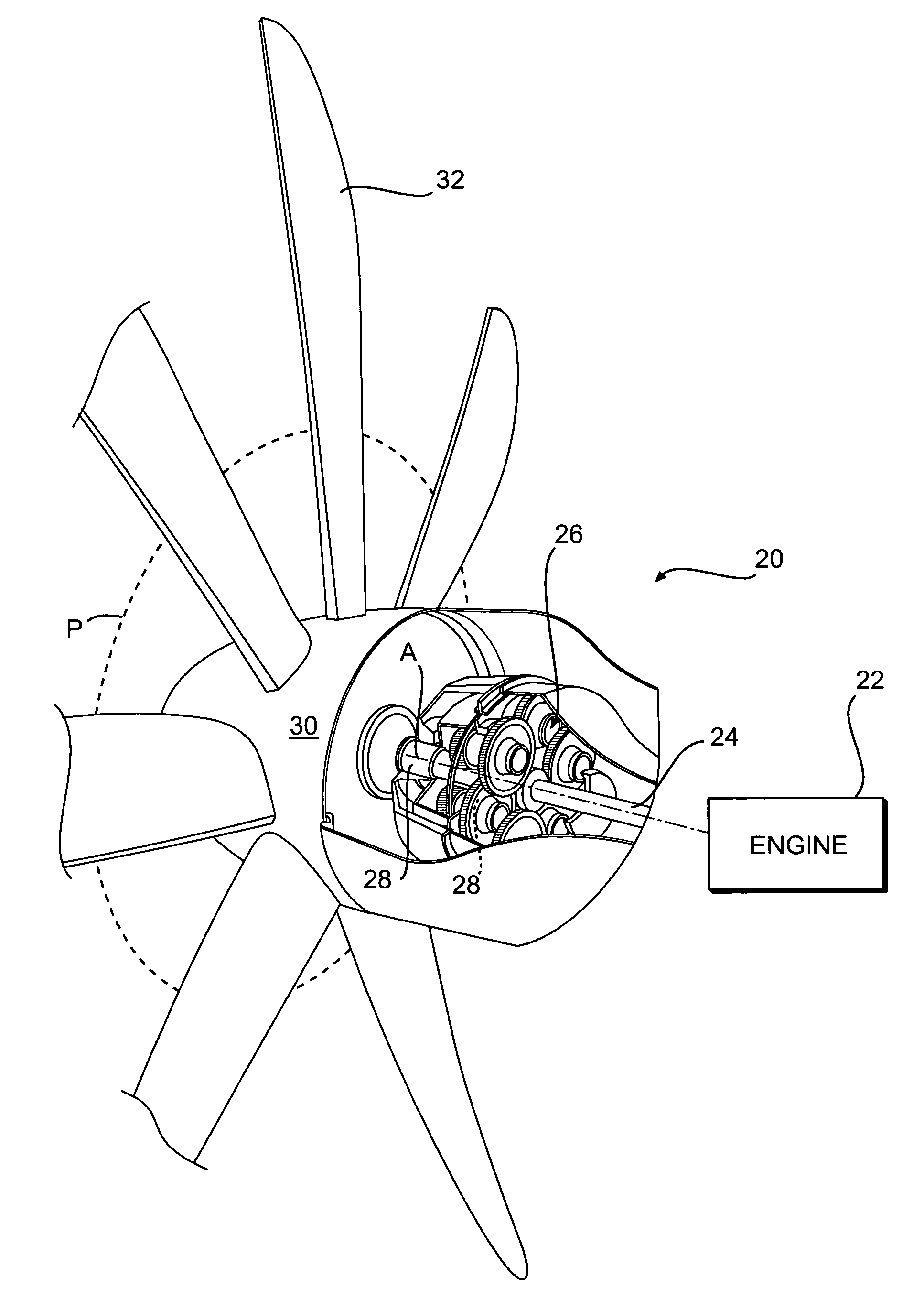
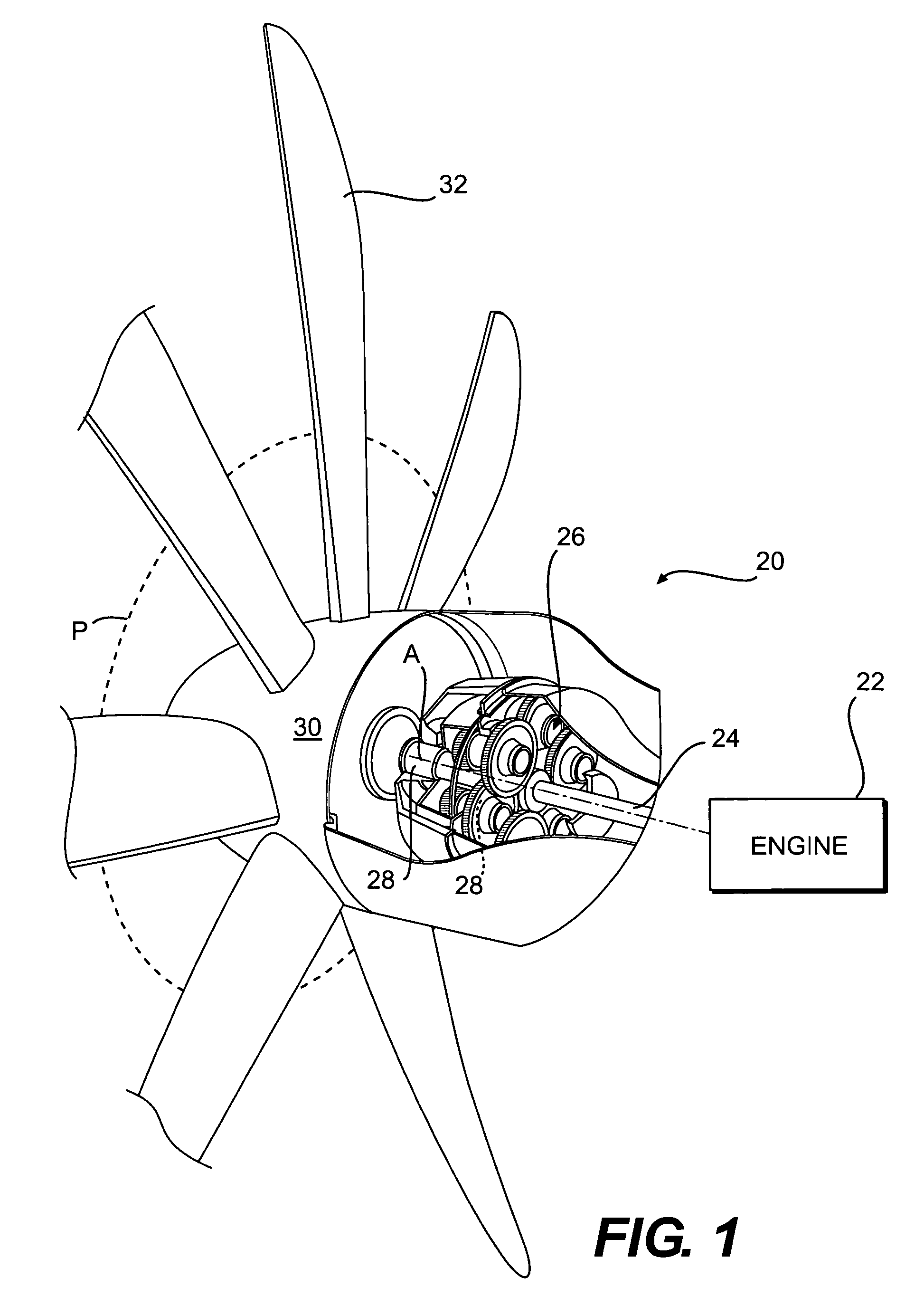
[0016]FIG. 1 illustrates a general perspective view of a propeller system 20 driven by a gas turbine engine (illustrated schematically at 22) which rotates a turbine output shaft 24 at a high speed. The turbine output shaft 24 drives a gear reduction gearbox (illustrated somewhat schematically at 26) which decrease shaft rotation speed and increase output torque. The gearbox 26 drives a propeller shaft 28 which rotates a propeller assembly hub 30 with a plurality of blade assemblies 32 which extend therefrom.

[0017]Axis A is substantially perpendicular to a plane P which is defined by the blade assemblies 32. It should be understood that although a propeller system typical of a turboprop aircraft is illustrated in the disclosed embodiment, various prop / rotor systems including tilt rotor and tilt wing systems will benefit from the present invention.

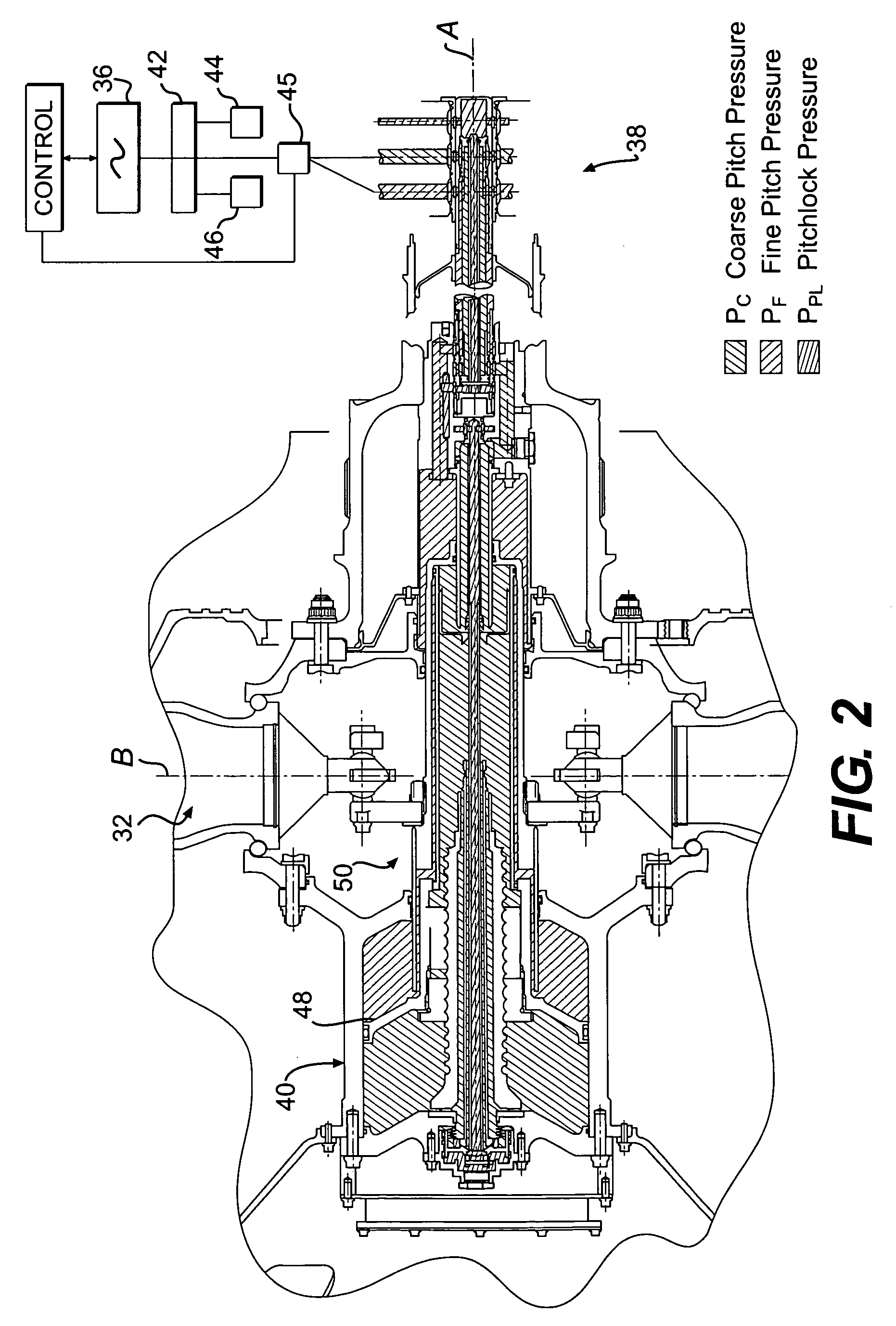
[0018]Referring to FIG. 2, a schematic sectional view of the propeller system 20 is illustrated. A main pump 36, for actuating the various...


PUM


Abstract

A pitch change system includes a yoke assembly which receives a pitch trunnion that extends from each propeller blade assembly. Each pitch trunnion is received within a respective bearing assembly mounted in the yoke assembly. The bearing assemblies are mounted between a forward yoke plate and an aft yoke plate. A spacer is mounted between each adjacent bearing assembly to position and restrain each bearing assembly. Each spacer includes an extension which retains the adjacent bearing assembly on a pitch trunnion pin in a direction generally parallel to axis. Each of the bearing assemblies includes a generally rectilinear outer race and a spherical inner race inside diameter to receive the pitch trunnion pin. The rectilinear outer race reduces contact stresses to acceptable levels for high load applications yet permits blade installation without actuator disassembly.

Description

BACKGROUND OF THE INVENTION[0001]The present invention relates to a propeller system, and more particularly to a bearing system for a pitch change system therefor.[0002]Typical propeller pitch change systems utilize a scotch yoke type mechanism to convert linear motion of a hydraulic piston into the rotational motion of the propeller blades such that a dynamic interface is required between the propeller blade pin, roller bearing and the yoke assembly. As horsepower increases, the loads imposed on the pitch change system correspondingly increase. This increase in load necessarily requires a size increase in the pitch change components due to the high contact stresses associated with the interaction of the roller bearings with the yoke assembly. Increasing roller size to reduce the contact stress to a reasonable level eventually becomes size prohibitive with regard to maintenance and assembly. That is, blade removal would be prohibited as the roller becomes too large to pass through t...

Claims


Application Information

Patent Timeline
Patent Type & Authority Patents(United States)
IPC IPC(8): B64C27/50
CPCB64C11/38B64C11/06
Inventor RAES, MARK R.CARVALHO, PAUL A.
Owner HAMILTON SUNDSTRAND CORP
Why Eureka
Try Eureka