Embedded igniter system for internal combustion engines

a technology of internal combustion engine and igniter, which is applied in the direction of engine ignition, machines/engines, and combustion explosion, can solve the problems of inability to endure the heat range associated with the inability of the spark electrode to be exposed to the chamber, and the undesirable effect of the thickness of the metallic plate on the area of the combustion chamber, so as to reduce the octane fuel requirements of internal combustion engines, eliminate the homogeneity, and eliminate the effect of the auto

Inactive Publication Date: 2007-11-27
BROWNE BRUCE D +1
View PDF9 Cites 37 Cited by
  • Summary
  • Abstract
  • Description
  • Claims
  • Application Information

AI Technical Summary

Benefits of technology

[0028]Another object of the invention is to eliminate the homogeneity, emphasis and narrow focus upon varying spark plug heat range requirements of conventional internal combustion engines.
[0029]Still another object of the embedded igniter system is to eliminate the auto advance on conventional internal combustion engines by sequentially a...

Problems solved by technology

The burning of fuel in the conventional internal combustion engines has been improved in recent years due to regulations but is no where close to a complete burn of the fuel/air mixture, which is a major contributor to our air pollution problem.
The problem may be exacerbated by timing advance, which could cause the combustion to explode early enough to deter the piston from reaching top dead center.
The thickness of the metallic plate will have an undesirable effect on the area of the combustion chamber.
The spark electrodes exposed to the chamber will not be ab...

Method used


Image

  • Embedded igniter system for internal combustion engines
  • Embedded igniter system for internal combustion engines
  • Embedded igniter system for internal combustion engines

Examples


Embodiment Construction

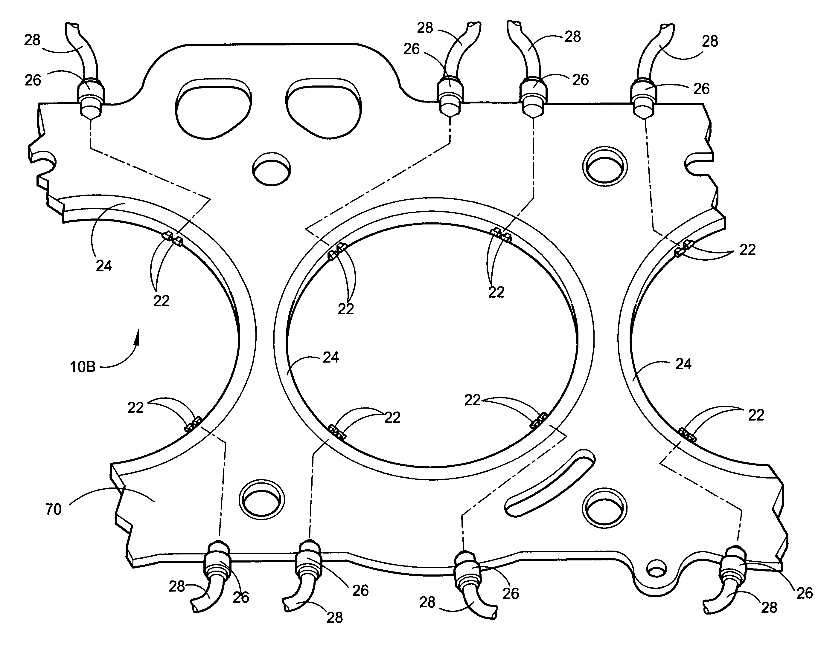
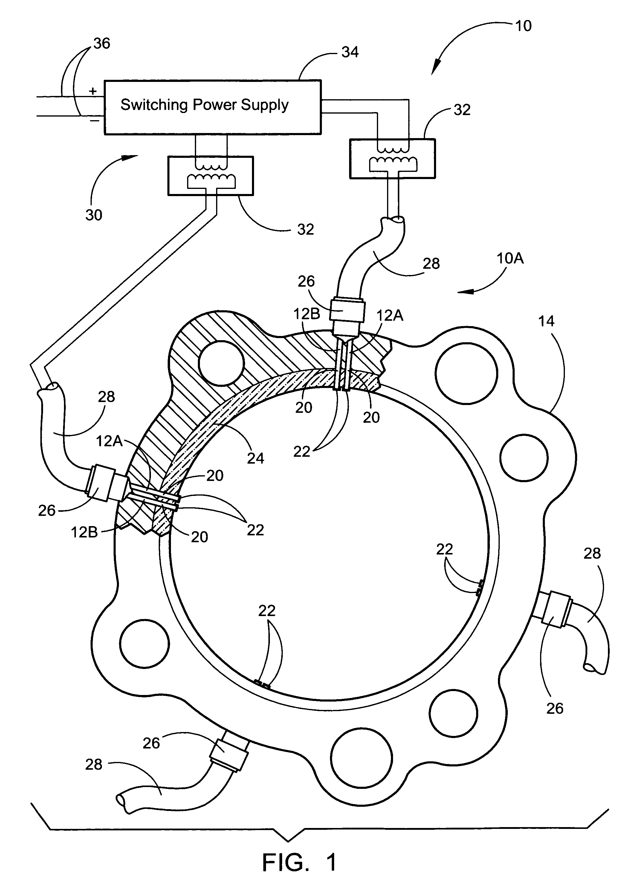
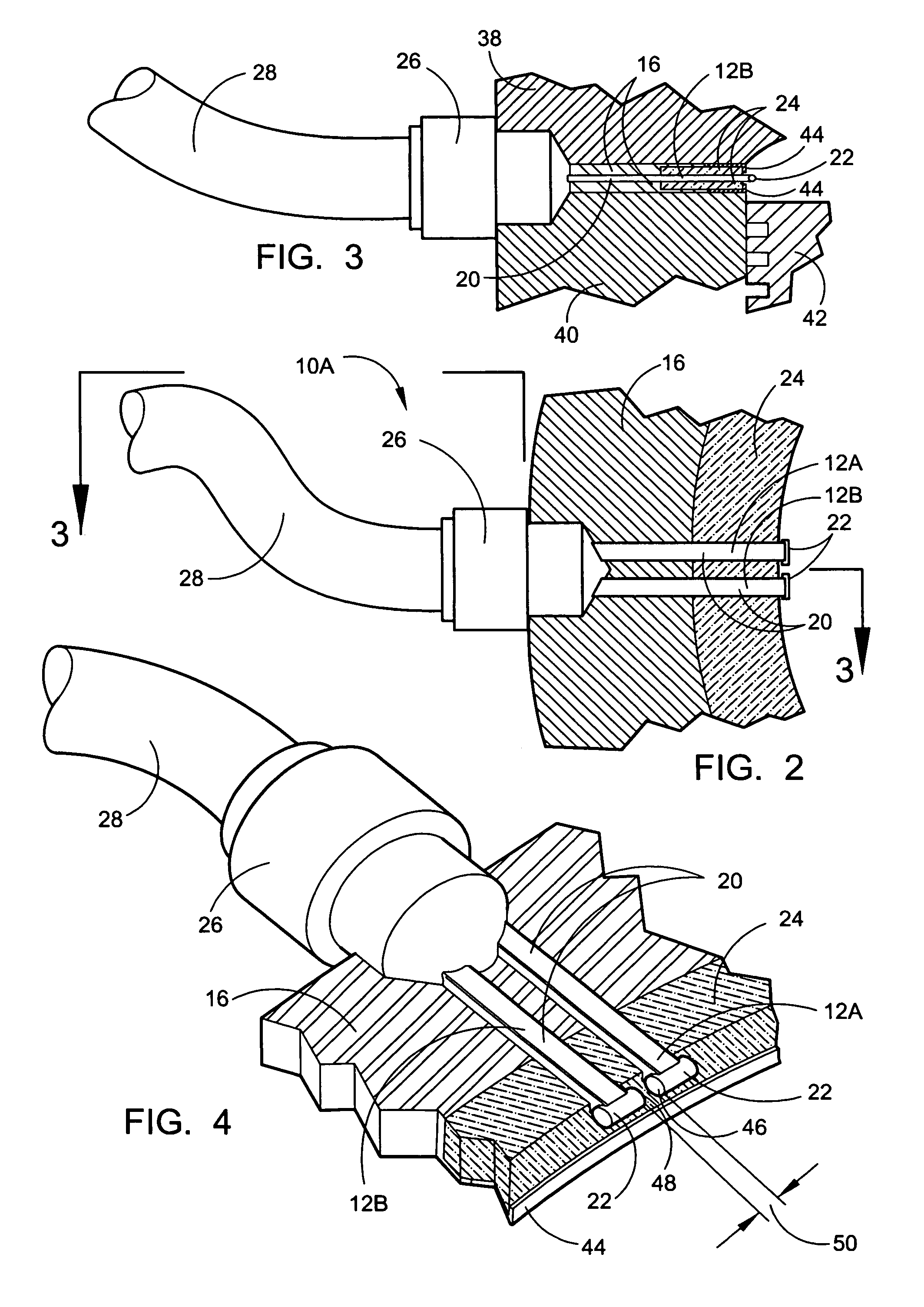
[0054]Referring now to the drawings, wherein similar parts of the embedded igniter system 10 for internal combustion engines are identified by like reference numerals, there is seen in FIG. 1 four pairs of embedded igniters 12 embedded into a single cylinder head gasket 14. The cylinder head gasket 14 is composed of layers of dielectric polyamide materials 16 and carbon fiber materials 18. The primary igniter 12A and the secondary igniter 12B consist of rectangular tantalum bars 20 with iridium electrode pins 22 at the ends encased in an alumina ceramic insulation housing 24. The rectangular shape of the tantalum bar 20 insures a means that they will not rotate within the alumina ceramic insulation housing 24 although a variety of other geometric shapes will insure the anti-rotation feature, including square, and they all will be covered within the scope of this patent.

[0055]In the simplest embodiment of the embedded igniter system 10A depicted in FIG. 1, the tantalum bars 20 are di...


PUM


Abstract

An embedded igniter for internal combustion engines consisting of a multiple ignition system with separate control for individual pairs of igniters that has been designed to replaces the spark plugs of internal combustion engines. This device allows for a more complete burn of the fuel/air mixture within the combustion chamber. The embedded igniter system will consist of one or more igniter units consisting of a pair of rectangular tantalum bars with iridium electrode pins at the ends. The paired igniter pins are encased in alumina ceramic, a high dielectric/high temperature housing positioned around the combustion chamber holding and insulating the electrodes relative to their position in reference to the combustion chamber. One or more igniter units may be incorporated around each cylinder opening of a head gasket made from a composite of polyamide, carbon fiber and copper or equivalent material or may be incorporated into an internal combustion engine that does not require a head gasket.

Description

FIELD OF THE INVENTION[0001]This invention relates to the field of the spark ignition systems on internal combustion engines with one or more cylinders where a spark is required to ignite a combustible fuel / air mixture. In general, this patent replaces the spark plugs of internal combustion engines with one or more pairs of individually controlled embedded igniters.BACKGROUND OF THE INVENTION[0002]In a wide variety of internal combustion engines the fuel ignition characteristics have become important from the viewpoints of fuel consumption and exhaust gas emissions. With the rising costs of oil and the air pollution problems, it has become imperative that new methods of saving fuel and having a cleaner more complete burn within the combustion chamber be devised. In order to attain lower, more efficient fuel consumption it is necessary to increase the combustion efficiency of the internal combustion engines. The spark plugs used in internal combustion engines have not changed signifi...

Claims


Application Information

Patent Timeline
IPC IPC(8): F02P15/08F02P15/02H01T13/46
CPCF02P15/02H01T13/467F02P15/08
Inventor LEE, LARRY C.
Owner BROWNE BRUCE D
Why Eureka
Try Eureka