On-board inert gas generation system with compressor surge protection

a technology of inert gas and surge protection, which is applied in the direction of energy-efficient board measures, auxillary pretreatment, separation processes, etc., can solve the problems of reducing the inlet pressure of the module greatly increasing the weight of the module, affecting so as to achieve the effect of increasing the reliability of the system and simplifying the system

Active Publication Date: 2007-11-27
HAMILTON SUNDSTRAND CORP
View PDF5 Cites 30 Cited by
  • Summary
  • Abstract
  • Description
  • Claims
  • Application Information

AI Technical Summary

Benefits of technology

[0009]In this manner, the system is simplified by eliminating an actuator and providing increased reliability to the system in the event of a failure of the actuator.

Problems solved by technology

Lowering the inlet pressure to the module greatly increases its weight.
Surge can damage or destroy a compressor.
Surge can be difficult to avoid since on-board inert gas generation systems typically operate under a wide range of flow rates.
If the surge control valve fails when the nitrogen enriched valve is in a small area position then a surge condition will result in the first compressor leading to a mechanical failure of the compressor.

Method used


Image

  • On-board inert gas generation system with compressor surge protection
  • On-board inert gas generation system with compressor surge protection
  • On-board inert gas generation system with compressor surge protection

Examples


Embodiment Construction

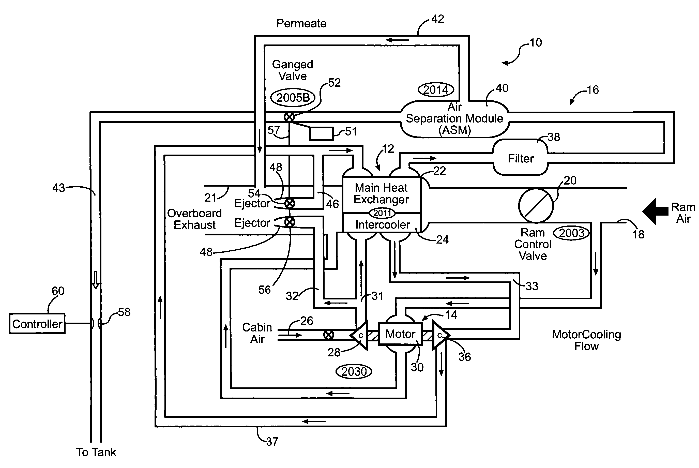
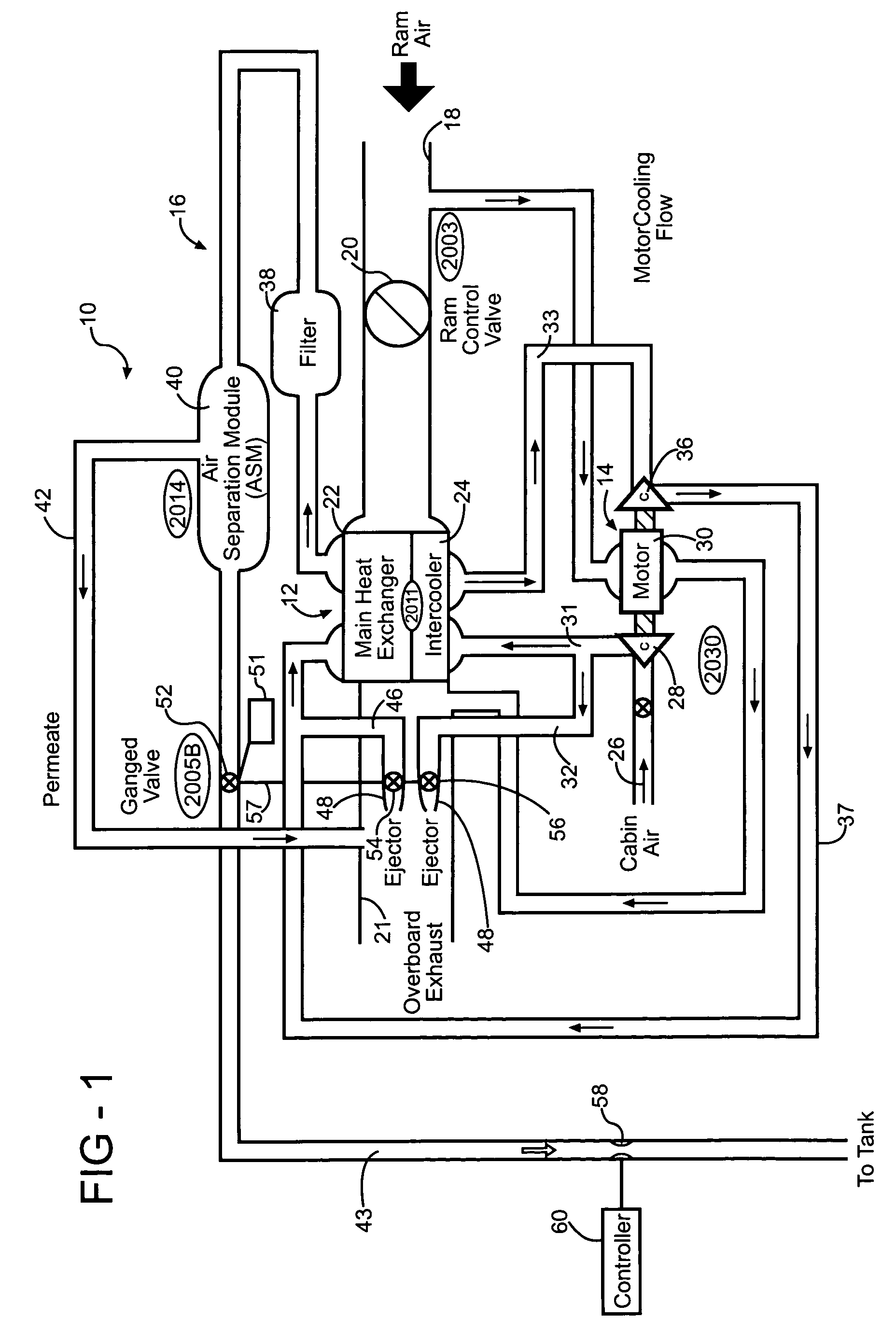
[0013]FIG. 1 is a highly schematic depiction of one example of an inventive on-board inert gas generation system 10. The system 10 includes a heat exchanger system 12 that removes heat generated by compressed air from a compressor system 14. The compressed air provides pressurized air to an air separation module system 16.

[0014]The heat exchanger system 12 is arranged between a ram air inlet duct 18 and a ram air outlet duct 21. Flow through the ram air ducts 18 and 21 is regulated by a control valve 20 arranged between the ram air inlet duct 18 and the heat exchanger system 12.

[0015]Air 26 enters the system 10, for example from the cabin, into a first compressor 28 of the compressor system 14. The first compressor 28 is driven by an electric motor 30. The compressed air exits the first compressor 28 and flows through a passageway 31 through an intercooler 24 of the heat exchanger system 12 where the ram air removes the heat from the compressed air.

[0016]Cooled air from the intercoo...


PUM

PropertyMeasurementUnit
areaaaaaaaaaaa
pressureaaaaaaaaaa
pressuresaaaaaaaaaa

Abstract

A valve assembly includes a nitrogen enriched airflow control valve, a first stage surge control valve and a second stage surge control valve respectively arranged in a passage downstream of an air separation module, and in first and second surge control passages. The valves are in a ganged relationship or connected to one another such they move with one another in response to an input from a common actuator. The surge control valves open as the nitrogen enriched airflow control valve is moved to provide a smaller area.

Description

BACKGROUND OF THE INVENTION[0001]This invention relates to an on-board inert gas generation system. Specifically, the invention relates to a method and apparatus for increasing the pressurized air provided to an air separation module of the system.[0002]On-board inert gas generation systems are increasingly used in aircraft to provide inert gas to various locations such as the cargo area or fuel tanks. Typically, the system includes two compressors or stages arranged in series for providing compressed air to the air separation module. It is desirable to provide high pressures to the air separation module to reduce the weight of the module. Lowering the inlet pressure to the module greatly increases its weight.[0003]Centrifugal compressors are typically used in the system to provide compressed air to the module. It is desirable to ensure that the compressors do not operate in a surge condition, which is a transient phenomenon that occurs when flow through the compressors is reduced b...

Claims


Application Information

Patent Timeline
Patent Type & Authority Patents(United States)
IPC IPC(8): B01D53/22
CPCB64D13/06B64D37/32Y02T50/56B64D2013/0677Y02T50/44B64D2013/0644Y02T50/40Y02T50/50
Inventor SCHWALM, GREGORYSURAWSKI, ERICSCHWEMMER, JOHNDION, MARK
Owner HAMILTON SUNDSTRAND CORP
Why Eureka
Try Eureka