Radio communication method and system for performing communication among a plurality of radio communication terminals

a radio communication terminal and communication method technology, applied in the direction of synchronisation arrangement, oscillator generator, wireless commuication services, etc., can solve problems such as difficulties in configuring a radio communication system, and achieve the effects of large phase noise, high-quality signal transmission, and large phase nois

Inactive Publication Date: 2007-11-27
NAT INST OF INFORMATION & COMM TECH
View PDF11 Cites 2 Cited by
  • Summary
  • Abstract
  • Description
  • Claims
  • Application Information

AI Technical Summary

Benefits of technology

[0008]Alternatively, in the present invention, one of the terminals serves as a master station; a local oscillation signal used in the master station is transmitted to the air as a reference local oscillation signal; and each of the remaining radio communication terminals receives the reference local oscillation signal. After amplification and band-pass filtering, the received reference local oscillation signal is fed to an injection locked oscillator so as to reproduce the local oscillation signal synchronously with the reference local oscillation signal of a proper level. The thus-reproduced signal is used as a local oscillation signal for frequency conversion in the transmission section and the reception section. This configuration enables all the terminals within the network to generate and receive millimeter wave signals which are synchronized in frequency and phase. Further, even in the case where the reference local oscillation signal is produced by inexpensive means and has large phase noise and frequency offset, their influences are cancelled out as a result of transmission and reception between terminals, whereby high-quality signal transmission becomes possible.
[0009]Moreover, in the present invention, each of the radio communication terminals is configured to serve as a base station or a master station. Therefore, without provision of a special reference signal transmission station or base station, a network which enables high-quality communications can be produced instantly at any location.

Problems solved by technology

However, several problems arise in a radio communication system configured for N to N communications among N terminals.
That is, although the above-mentioned two-way radio communication system and method are effective for two-way (bi-directional) communications between two terminals, when the number of terminals increased to N, difficulty is encountered in configuring a radio communication system which solves a problematic signal deterioration caused by an employed local oscillation signal and which effectively uses a frequency.

Method used


Image

  • Radio communication method and system for performing communication among a plurality of radio communication terminals
  • Radio communication method and system for performing communication among a plurality of radio communication terminals
  • Radio communication method and system for performing communication among a plurality of radio communication terminals

Examples


first embodiment

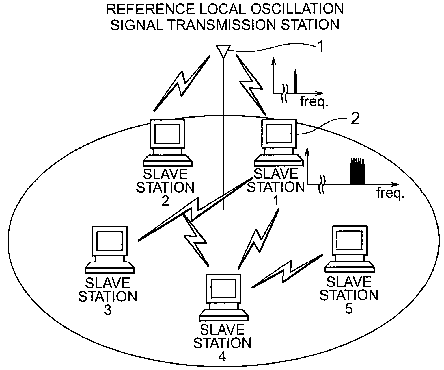
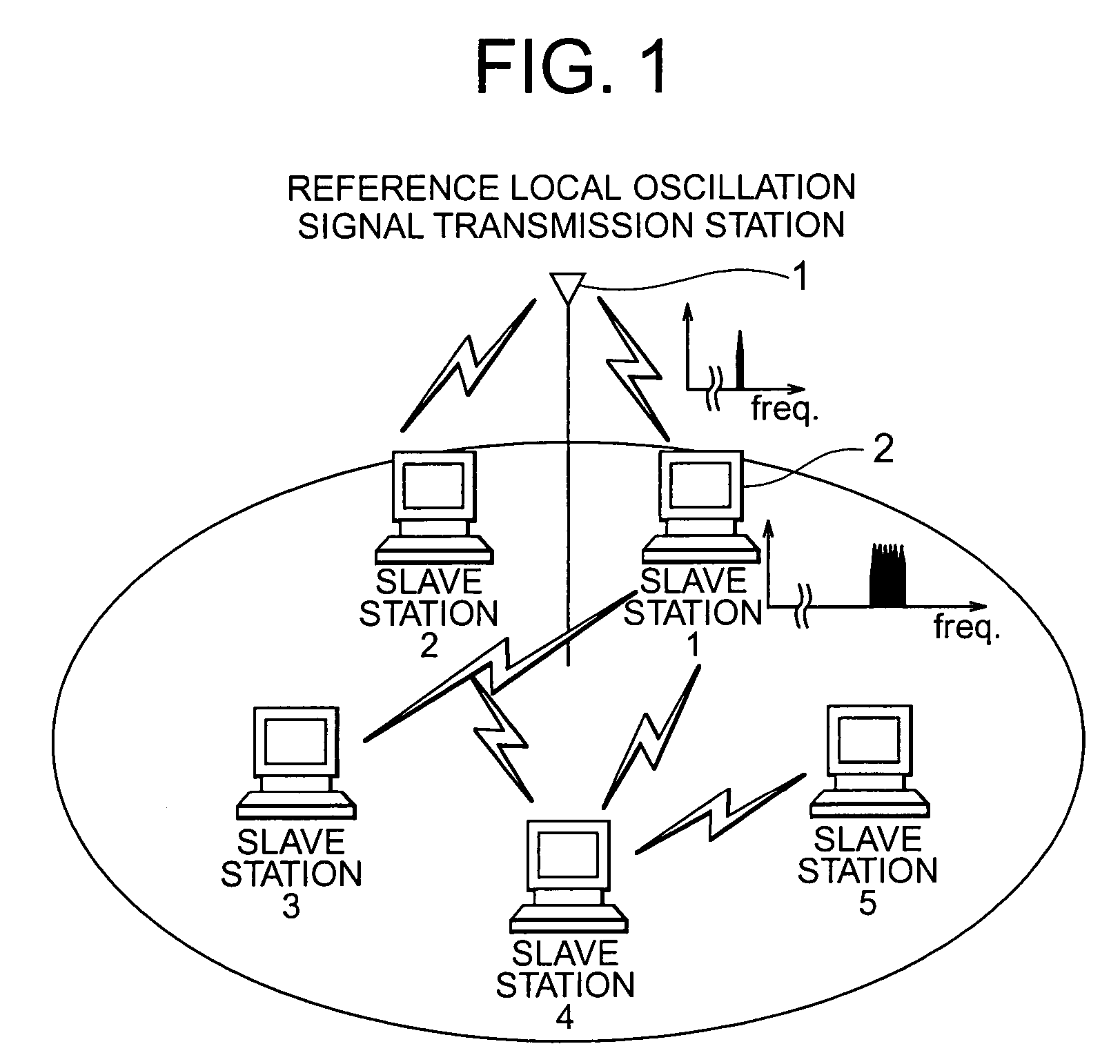
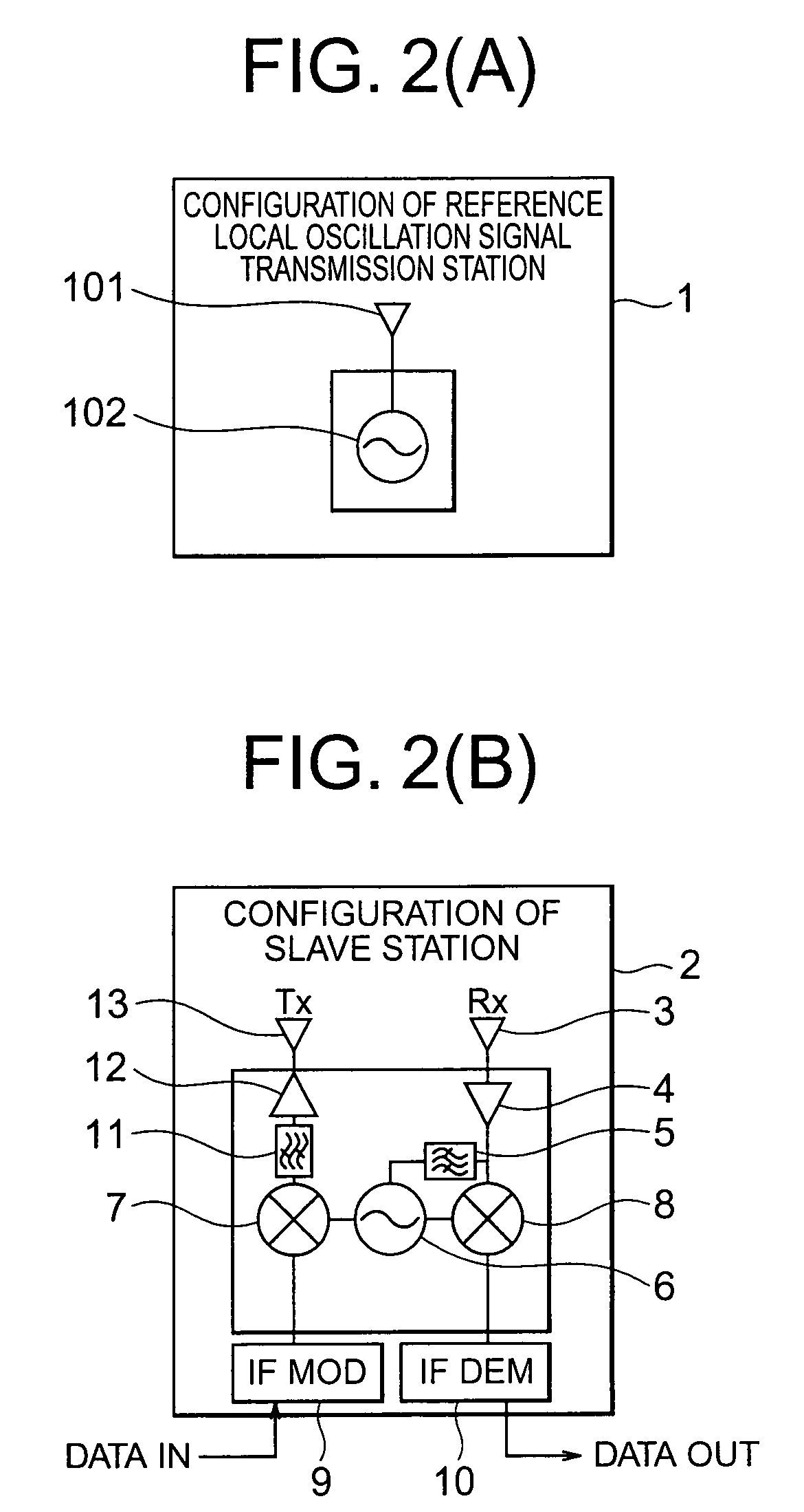
[0017]FIG. 1 shows the configuration of a radio communication system according to a first embodiment of the present invention, along with transmission signal spectrum of each station. FIGS. 2(A) and 2(B) respectively show the specific configurations of a reference local oscillation signal transmission station and a slave station of the radio communication system of the first embodiment. A reference local oscillation signal transmission station 1 radiates a reference local oscillation signal generated at a reference local oscillator 102 to a service zone via a transmission antenna 101. Each radio slave station terminal 2 (slave station No. 1, slave station No. 2, slave station No. 3, etc.) receives the reference local oscillation signal via an antenna 3. The received reference local oscillation signal is amplified by means of an amplifier 4, and a portion of the amplified reference local oscillation signal is passed through a band-pass filter 5 for removal of unnecessary waves and is...

second embodiment

[0019]FIG. 3 shows the configuration of a radio communication system according to the second embodiment of the present invention, along with the transmission signal spectrum of each station. FIGS. 4(A) and 4(B) respectively show the specific configurations of a base station and a slave station of the radio communication system of the second embodiment. In a base station 14, an IF band modulated signal received from an IF band modulated signal generator 15 is fed to a mixer 17, to which a signal from a local oscillator 16 is supplied. Thus, the IF band modulated signal is converted to a signal in the radio frequency band. The thus-obtained radio signal is passed through a band-pass filter 18 so as to remove unnecessary wave components therefrom. A portion of a local oscillation signal, which serves as a reference local oscillation signal within the network, is added to the radio signal. A resultant radio signal is amplified by means of an amplifier 19 and is then transmitted from an ...

third embodiment

[0021]FIG. 5 shows the configuration of a radio communication system according to a third embodiment of the present invention, along with the transmission signal spectrum of each station. FIGS. 6(A) and 6(B) respectively show the specific configurations of a slave station (master mode) and a slave station (slave mode) of the radio communication system of the third embodiment. The present radio communication system consists of a plurality of slave station terminals (slave station No. 1, slave station No. 2, slave station No. 3, etc.). However, each of the terminals is designed in such a manner that it can selectively assume either of two states; i.e., a master mode and a slave mode, and that, in a single network, only one slave station can operate in the master mode, that slave station being determined by a protocol of an upper layer with resect to the physical layer. In a slave station 37 having entered the master mode, a switch 38 is switched to a master mode side by means of a swi...


PUM


Abstract

A reference local oscillation signal transmission station 1 radiates a reference local oscillation signal to a service zone. A portion of the signal received by each radio slave station terminal 2 is branched and fed to an injection locked oscillator 6. As a result, a local oscillation signal which is synchronized with the reference local oscillation signal is obtained. In the slave station terminal 2, the thus-obtained local oscillation signal is fed to a transmission frequency converter (mixer) 7 and a reception frequency converter (mixer) 8. An IF band transmission modulated signal is fed to the mixer 7 for frequency conversion to a radio frequency band, and the thus-obtained radio-frequency modulated signal is transmitted. Meanwhile, a received radio-frequency modulated signal is fed to the mixer 8 for down conversion, and the thus-obtained signal is fed to an IF band demodulator 10 so as to restore an information signal. The present invention not only solves the problem of deterioration of signal quality stemming from phase noise and frequency offset generated in a millimeter wave band oscillator, but also improves the efficiency of frequency use.

Description

TECHNICAL FIELD[0001]The present invention relates to a radio communication method and system for communications between a plurality of radio communication terminals.BACKGROUND ART[0002]A radio communication apparatus for transmitting a high-speed digital signal or a broadband analog signal generally consists of a transmitter in which a product of an intermediate-frequency-band modulated signal (IF) and a local oscillation signal (LO) is obtained for up conversion, and a thus-generated radio-frequency modulated signal (RF) is transmitted; and a receiver in which a product of an RF and an LO is obtained for down conversion, whereby an IF is produced. In such a case, in order to maintain the quality of a transmitted signal, the IF input to the transmitter and the IF generated in the receiver must have a known constant frequency difference therebetween, and variation in the phase difference with time must be small. Therefore, local oscillators for generating the LOs in the transmitter ...

Claims


Application Information

Patent Timeline
Patent Type & Authority Patents(United States)
IPC IPC(8): H04B1/00H04B7/00H03B1/04H03B5/12H04B1/26H04B1/40H04L12/28H04W56/00H04W84/12
CPCH04B1/405H03B2202/027H04B1/40H04B1/26H04L12/28
Inventor SHOJI, YOZOHAMAGUCHI, KIYOSHIOGAWA, HIROYO
Owner NAT INST OF INFORMATION & COMM TECH
Why Eureka
Try Eureka