Method and arrangement for automated control of a vehicular drive train

a technology of automated control and drive train, which is applied in the direction of transportation items, instruments, tractors, etc., to achieve the effect of enhancing the method effect and enhancing the effectiveness of vehicle amplification

Active Publication Date: 2007-11-27
VOLVO LASTVAGNAR AB
View PDF10 Cites 31 Cited by
  • Summary
  • Abstract
  • Description
  • Claims
  • Application Information

AI Technical Summary

Benefits of technology

[0009]In a general sense, the present invention is modeled to mimic those strategies that experienced drivers have developed for achieving vehicle start-up or launch when travel-impeding conditions are encountered as described hereinabove. These conditions include, but are not limited to loose and muddy soil, and uneven terrain having depressions and troughs, and ridges and rises, that can be difficult for a heavy-duty vehicle to surmount upon launch from a stand-still position, or slow-moving operation. In that drive trains of most land vehicles, and especially heavy-duty vehicles, have at least semi-automated control systems, the present invention provides an automated control strategy, that when implemented, enables any operator, regardless of experience level, to maximize the capabilities of his or her vehicle to be driven out of stuck conditions, and other situations that otherwise make launching into travel difficult.
[0025]According to one embodiment, the step of transmitting power to a drive wheel includes at least one of the following steps: (1) engaging a gear of an automatic transmission of the drive train in the desired travel direction; (2) controlling an engine of the drive train to increase the engine torque; and / or (3) engaging a main clutch of the drive train. Advantageously, control of the engine can include controlling the engine torque as a function of the degree of depression imparted to the accelerator pedal by the driver. In this manner, the driver can determine how much power is to be transmitted to the drive wheel(s). This feature also provides to the operator a feeling of control over the vehicle that might otherwise be lost in a completely independent control routine. This is particularly useful when the vehicle exits the automated off-road start-up procedure.
[0033]Preferably, several conditions can be monitored simultaneously, and one or more considered in the control routine. Depending on the type of vehicle, additional features can be incorporated into the routine to enhance the effects of the method. Examples include engaging a lateral differential lock of the drive train; enabling a traction control procedure controlling individual wheel brakes for reducing the difference between a right drive wheel speed and a left drive wheel speed; inhibiting a traction control procedure of the vehicle that controls individual wheel brakes for reducing the difference between drive wheel speeds and non-driven wheel speeds; and engaging a longitudinal differential lock of the drive train.

Problems solved by technology

These conditions include, but are not limited to loose and muddy soil, and uneven terrain having depressions and troughs, and ridges and rises, that can be difficult for a heavy-duty vehicle to surmount upon launch from a stand-still position, or slow-moving operation.

Method used


Image

  • Method and arrangement for automated control of a vehicular drive train
  • Method and arrangement for automated control of a vehicular drive train
  • Method and arrangement for automated control of a vehicular drive train

Examples


Embodiment Construction

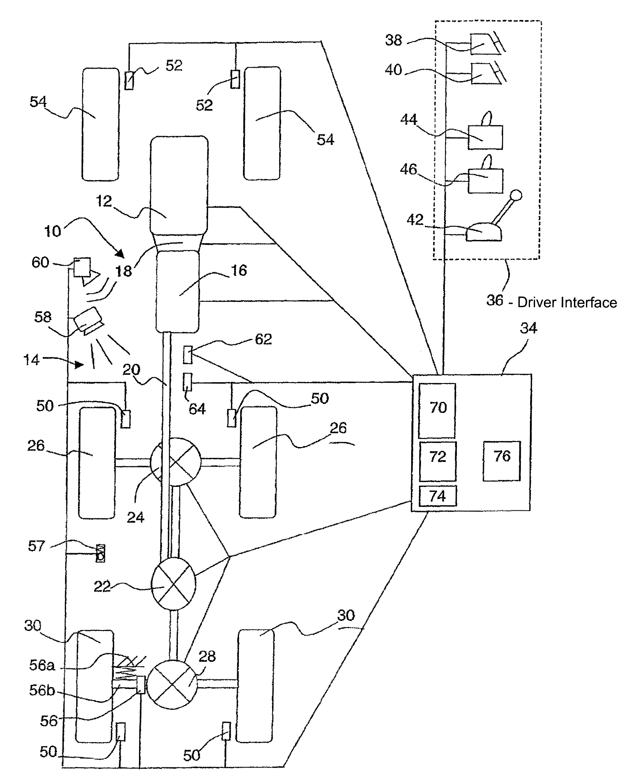
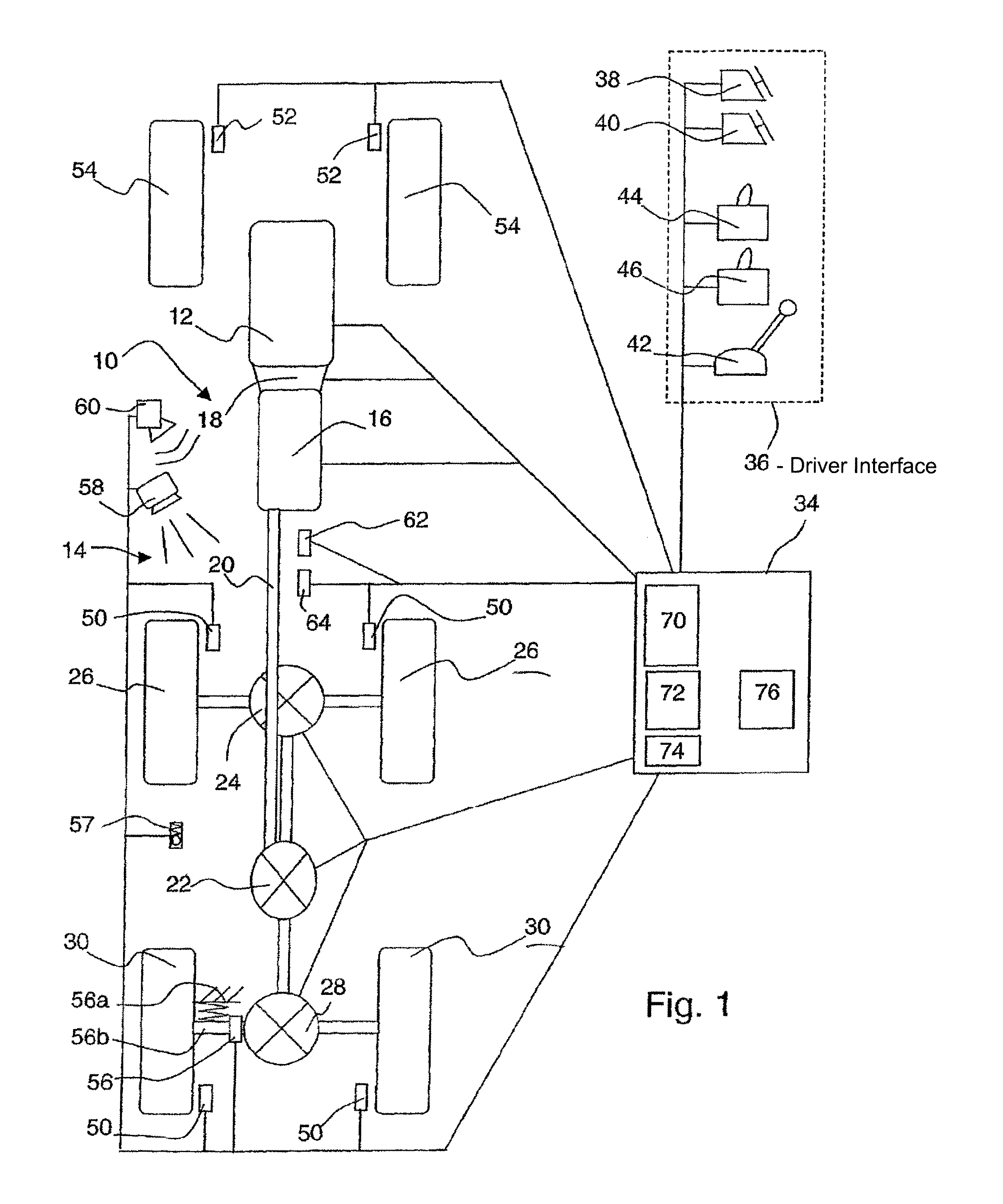
[0042]Referring to FIG. 1, a drive train 10 is shown including an internal combustion engine 12 and a driveline 14 for transmitting engine power to a first and a second set of drive wheels. The drive line 14 comprises (includes) an automatic transmission 16, a main clutch 18 positioned between the engine 12 and the automatic transmission 16, a propeller shaft 20 for transmitting power to a longitudinal transfer case 22 which transfers power to a first lockable transversal differential 24 for distributing the power to the first set of left and right drive wheels 26, and to a second lockable transversal differential 28 for distributing power to the second set of left and right drive wheels 30. The longitudinal transfer case is provided with a clutch or brake to discontinue power transmission to the first set of drive wheels 24. The transfer case may also be equipped to continuously change the ratio of power distribution between the first and second drive wheel sets. The driveline 14 c...


PUM


Abstract

Method and arrangement for automated control of a drive train (10) of a land vehicle to be executed when ground conditions exist that impede the initiation or continuation of travel of the vehicle such as being stuck on loose or slippery ground. The automated routine induces a rocking action in the vehicle purposed to aid in freeing the vehicle and permitting desired travel out of the area. As an initial step of the routine, it is determined whether such a ground condition exists. If so, drive power is applied, via a drive train (10) of the vehicle until the drive wheel (26, 30) bogs down or productive and continuous travel is established in the vehicle. A rocking-back action is permitted by a discontinuation of the drive power to the drive wheel (26, 30) of the land vehicle until a predetermined power resumption condition occurs. Reverse power can be optionally applied at this time. Otherwise, drive power is reapplied to the drive wheel (26, 30) for another attempt at forward progress. All of these actions are controlled via an automated drive train control routine that executes the method, typically responsive to a driver-initiated signal.

Description

CROSS-REFERENCE TO RELATED APPLICATIONS[0001]The present application is a continuation patent application of International Application No. PCT / SE2004 / 000625 filed 23 Apr. 2004 which was published in English pursuant to Article 21(2) of the Patent Cooperation Treaty, and which claims priority to Swedish Application No. 0301334-9 filed 7 May 2003. Said applications are expressly incorporated herein by reference in their entireties.TECHNICAL FIELD OF THE INVENTION[0002]The present invention relates to systems and methods for controlling the start-up or launch of a land vehicle, and more particularly to heavy-duty vehicles operating on unfavorable ground conditions such as those typically found off-road where travel paths can be littered with debris and eroded with holes and troughs or be composed of loose dirt.BACKGROUND ART[0003]Land vehicles, including automotive vehicles, and in particular heavy-duty vehicles such as logging trucks and trucks used on construction sites, when launche...

Claims


Application Information

Patent Timeline
Patent Type & Authority Patents(United States)
IPC IPC(8): G06F19/00B60K28/16B60W10/02B60W10/06B60W10/10B60W30/18F16H61/66
CPCB60K28/16B60K28/165B60W10/02B60W10/06B60W10/11B60W30/18045F16H61/66B60W30/18B60K2741/286Y10T477/6415B60W30/18172B60W2520/10B60Y2200/14F16H2312/08B60W10/10
Inventor STEEN, MARCUSERIKSSON, ANDERS
Owner VOLVO LASTVAGNAR AB
Why Eureka
Try Eureka