Line system for fluids having volatile components
a technology of volatile components and fluids, which is applied in the direction of liquid fuel feeders, braking systems, machines/engines, etc., can solve the problems of complex multi-layer structure of lines, expensive polymers, and difficulty in producing good adhesion of different types of polymer layers, and achieves the effect of simple production
- Summary
- Abstract
- Description
- Claims
- Application Information
AI Technical Summary
Benefits of technology
Problems solved by technology
Method used
Image
Examples
first embodiment
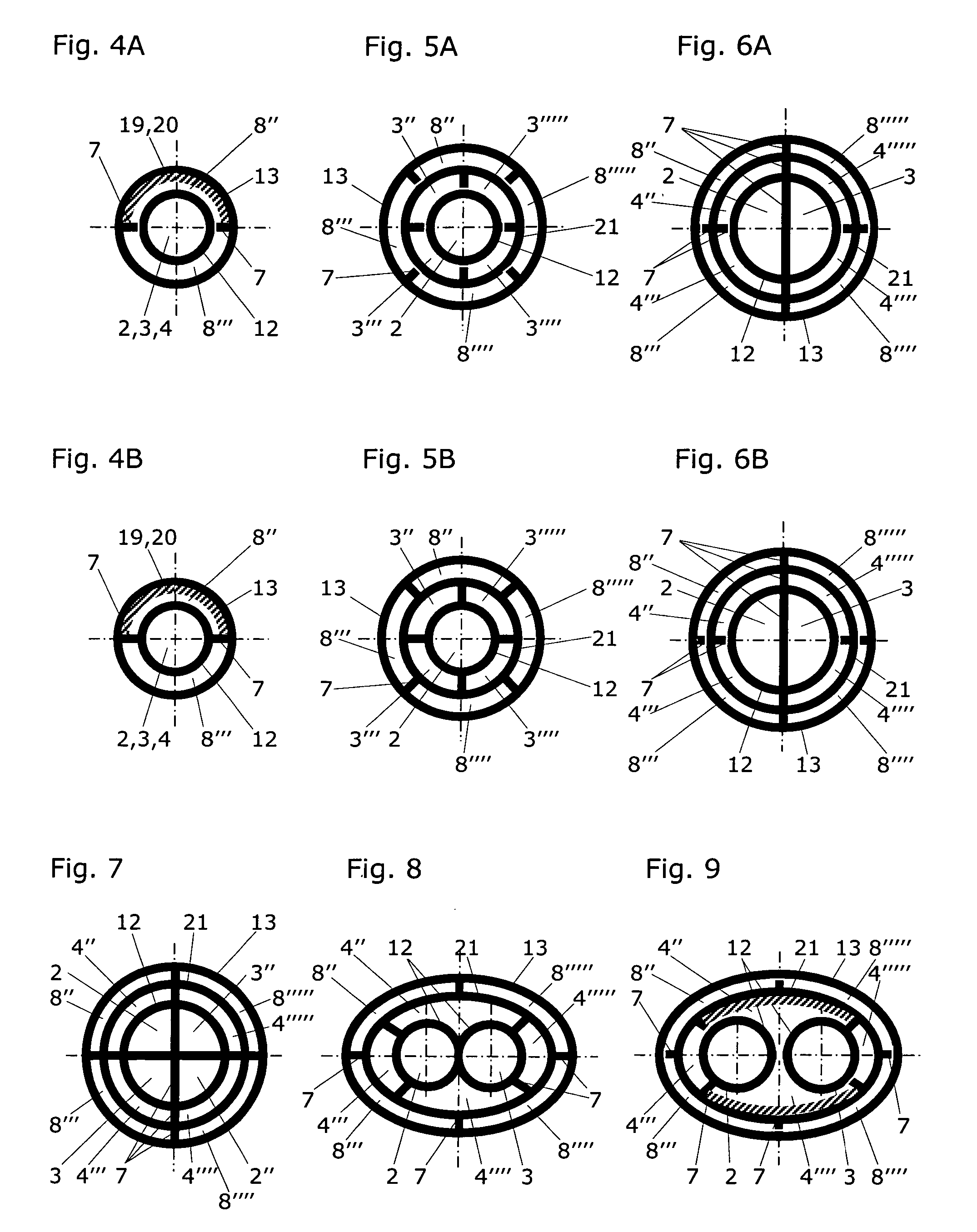
[0039]FIG. 4 shows a cross-section through the simplest, first embodiment of a line system 1 according to the present invention, which is implemented at least over the section A as a plastic hollow profile and comprises a scavenging line 8, which is enclosed by a second line wall 13. This scavenging line 8 comprises two scavenging chambers 8″, 8′″ here, which are separated from one another by support webs 7. The totality of these scavenging chambers 8″, 8′″ essentially encloses the fluid line 2,3,4. If one views the volume of the support webs 7 as belonging to the volume of the scavenging line 8, and particularly if (as shown in FIG. 4A) the first line wall 12 is separated from the support webs 7, the scavenging line 8 completely encloses the fluid line 2,3,4. This separation of the support webs 7 from the first line wall 12 is particularly preferred if greater flexibility of the plastic hollow profile is desired, for example, for thermoforming or laying on an automobile. Instead of...
second embodiment
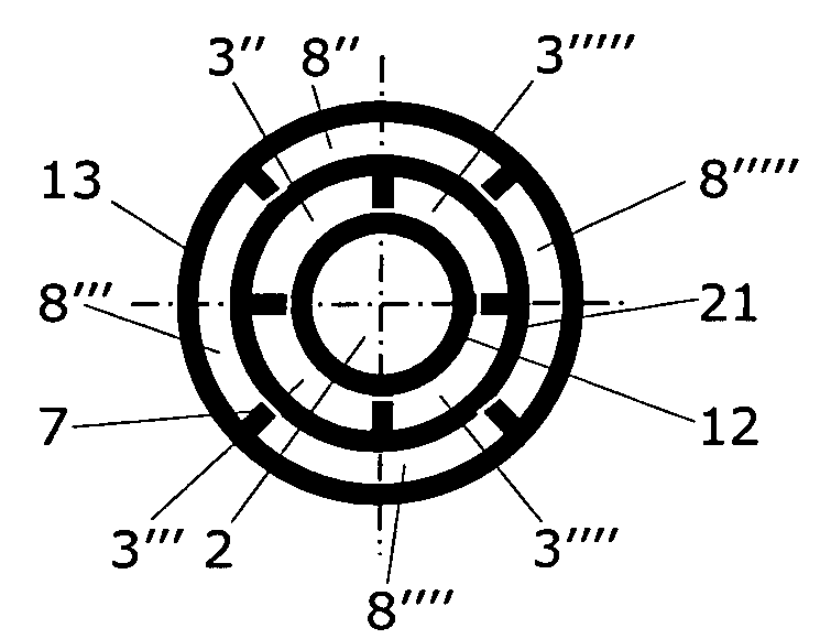
[0045]FIG. 5 shows a cross-section through the flow and return lines of a line system according to the present invention, according to a This is a line system 1 for fluids having volatile components, which comprises at least one fluid line (a flow line and a return line 2,3 here), each having a separate inlet 10 and outlet 11. These fluid lines 2,3 are enclosed by a first line wall 12 and extend—close-fitting to one another—jointly over a section A of the line system 1. The two fluid lines 2,3 are separated from one another at least by the first line wall 12 over their entire length. The two fluid lines 2,3 are enveloped by an intermediate wall 21. The cross-section shows that the line system 1 is implemented at least over the section A as a plastic hollow profile and comprises a scavenging line 8 situated around the intermediate wall 21. This scavenging line 8 is enclosed by a second line wall 13 and comprises one or more (four here) scavenging chambers 8″, 8′″, 8″″, 8′″″, which a...
third embodiment
[0046]FIG. 6 shows a cross-section through the flow, return, and ventilation lines of a line system according to the present invention, according to a In contrast to FIG. 5, here a ventilation line 4 is additionally situated concentrically, i.e., coaxially to the two fluid lines jointly forming a circular cross-section with the first wall 12. These fluid lines are identified here as the flow line 2 and as the return line 3 and are separated from one another by a support web 7. A ventilation line 4, comprising four line chambers 4″,4′″, 4″″, 4′″″, is situated around these fluid lines 2,3 and is delimited using an intermediate wall 21. All fluid lines 2,3,4 of the line system 1, which is implemented as a plastic hollow profile at least over the section A and comprises a scavenging line 8, are essentially enclosed by the scavenging line 8 and / or its scavenging chambers 8″,8′″,8″″, 8′″″, which are separated from one another by support webs 7. As shown in FIG. 6A, the first line wall 12...
PUM
 Abstract
Description
Claims
Application Information
 - R&D
- Intellectual Property
- Life Sciences
- Materials
- Tech Scout
- Unparalleled Data Quality
- Higher Quality Content
- 60% Fewer Hallucinations
Browse by: Latest US Patents, China's latest patents, Technical Efficacy Thesaurus, Application Domain, Technology Topic, Popular Technical Reports.
© 2025 PatSnap. All rights reserved.Legal|Privacy policy|Modern Slavery Act Transparency Statement|Sitemap|About US| Contact US: help@patsnap.com


