Apparatus and method for use in repairs of injured soft tissue

a technology of apparatus, which is applied in the field of apparatus and method for repairing torn or avulsed soft tissue, can solve the problems of pain, weakness and loss of function, torn free edge of tendon, poor quality tissue, etc., and achieves the effects of improving range of motion, promoting blood flow, and changing the stress on the injured soft tissu

Inactive Publication Date: 2007-12-04
DEAN & WEBB
View PDF38 Cites 342 Cited by
  • Summary
  • Abstract
  • Description
  • Claims
  • Application Information

AI Technical Summary

Benefits of technology

[0021]In another alternative embodiment of the present invention, the bridge member is adapted for selected, elastic longitudinal stretching of the bridge member after attachment. The ability for the bridge member to change length, thereby changing the stress on the injured soft tissue, may promote blood flow, increase range of motion, and minimize atrophy.
[0022]In yet further alternative embodiments of the present invention, each of the connector ends may be adapted or modified to accommodate other means of connection between an anchor member and the body, that are known to those of ordinary skill in the art or will be known to those of skill in the art in view of the prese

Problems solved by technology

In general, a torn rotator cuff, such as those shown in FIGS. 1 and 2, can lead to pain, weakness and loss of function.
The torn free edge of the tendon, however, can be poor quality tissue if it is subjected to the degenerative process that is commonly involved in these tears.
A common mode of failure on the soft side of the repair is the result of suture pullout or the pulling of sutures through the muscle or tendon.
While this is a stronger construct, there is a concern of strangulating the tissue with multiple weaves, resulting in necrosis of the tendon.
Also, this technique does not lend itself to arthroscopic repair of the tear.
This tendon augmentation has been shown to resist failure perpendicular to the tendon fibers but may not reduce tendon shear parallel to the fi

Method used


Image

  • Apparatus and method for use in repairs of injured soft tissue
  • Apparatus and method for use in repairs of injured soft tissue
  • Apparatus and method for use in repairs of injured soft tissue

Examples


Embodiment Construction

[0040]The present invention overcomes the shortcomings of current soft tissue repair techniques by incorporating one or more bridge members of selected length to accommodate proper attachment across injured tissue in connection with the repair of such tissue. For illustrative purposes of this document, embodiments of the present invention and methods for using embodiments of the present invention are described as it may be used to repair rotator cuff tears. Those skilled in the art will recognize that the present invention is capable of repair of other soft tissue injuries without departing from the spirit or scope of the present invention.

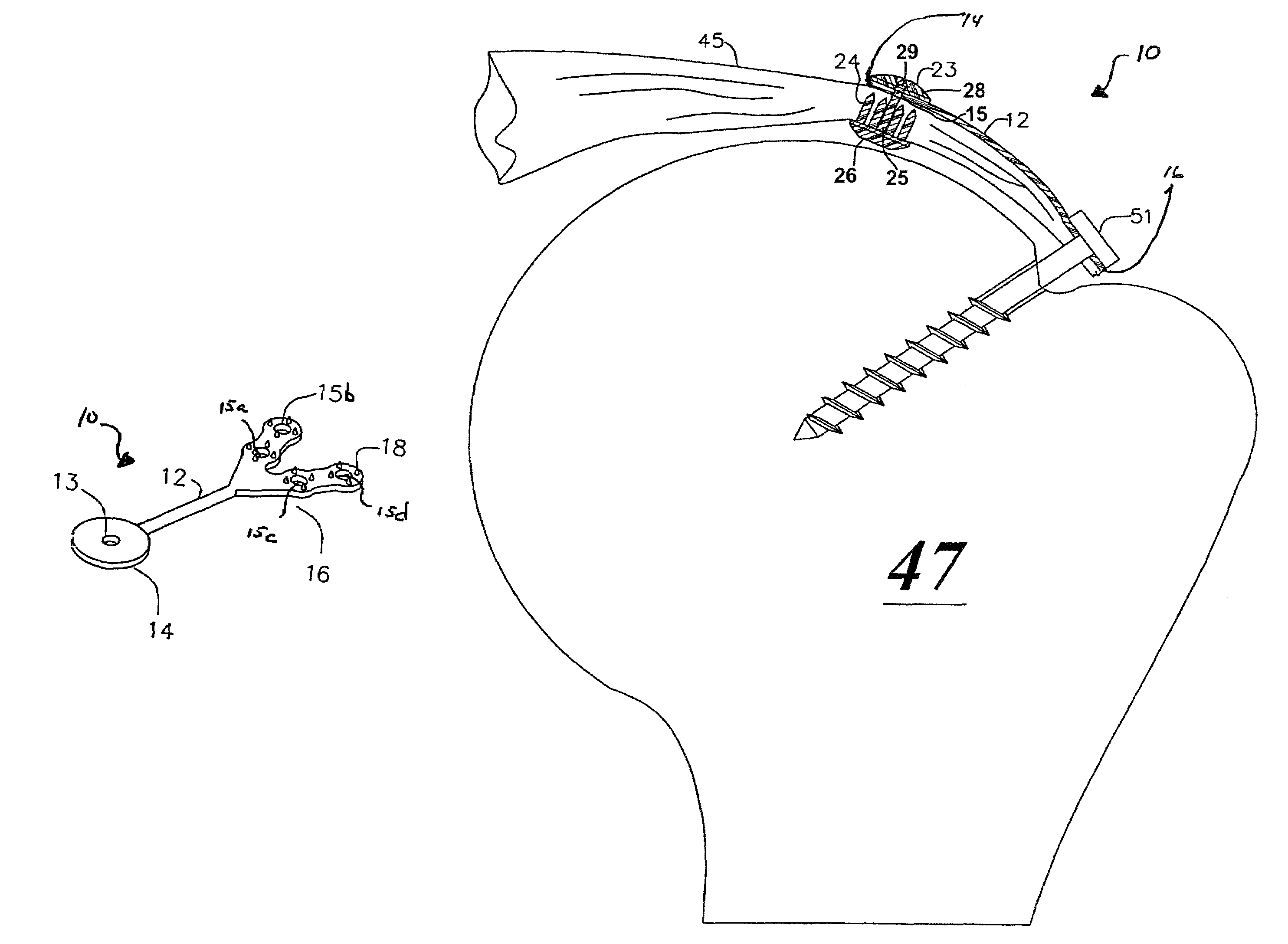
[0041]Referring to FIG. 4, the present invention generally comprises a bridge member 10 that includes a bridging section 12 to which is attached a first connector end 14 and a second connector end 16. The bridging section 12 is adapted with a selected length adequate to span the injured tissue and to provide attachment to healthy attachment points...


PUM


Abstract

A method, system and apparatus for augmenting the surgical repair of soft tissue injuries, in which a first end of a bridge member attaches to a first portion of healthy tissue, and a second end of the bridge member attaches to a second portion of healthy tissue. The bridge member (or bridge members) used to augment the soft tissue repair may be interconnected or function independently. Flexibility and elasticity of the bridge member are determined by the situation and may be altered to improve healing. The device may be used in arthroscopic procedures, and may be manufactured in a variety of lengths, or may be manufactured one length and be cut to the desired length, or otherwise altered to provide an optimal length of the bridge member.

Description

BACKGROUND OF THE INVENTION[0001]1. Field of the Invention[0002]The present invention relates to an apparatus and method for repairing torn or avulsed soft tissue. More particularly, the present invention relates to an apparatus and method for providing a connection between healthy bone or soft tissue and selected other healthy bone or soft tissue to accommodate a stable, secure attachment that selectively immobilizes or minimizes movement of intervening injured soft tissue so that the soft tissue may properly heal.[0003]2. Description of Related Art[0004]A relatively common type of injury, especially in connection with sports, is injury in which soft tissue is torn or avulsed from the bone. This type of injury occurs in connection with many types of orthopedic injuries, such as torn or ruptured tendons and / or ligaments. In the shoulder, this type of injury often takes the form of a torn rotator cuff in which a portion of the rotator cuff tendons tear within themselves or avulse fro...

Claims


Application Information

Patent Timeline
IPC IPC(8): A61B17/08
CPCA61B17/0401A61B17/0643A61F2/0811A61B2017/0412A61F2002/0864A61F2002/0829A61B2017/0427
Inventor DEAN, JOHN C.
Owner DEAN & WEBB
Why Eureka
Try Eureka