Interlocking mat

a technology of interlocking mats and locking devices, which is applied in the direction of screws, threaded fasteners, and ways. it can solve the problems of hazard to personnel and vehicles using the mats, the use of separately installed locking devices complicating the installation process, and the lock device can be lost or work its way out of the mat, so as to achieve the effect of optimum strength, convenient pin turning, and material saving benefits

Inactive Publication Date: 2007-12-04
SOLOCO LLC
View PDF17 Cites 122 Cited by
  • Summary
  • Abstract
  • Description
  • Claims
  • Application Information

AI Technical Summary

Benefits of technology

[0018]After insertion of the pin in the top-overlapping mat, the keeper feet pass through the slot in the upper lip with the offset midbody prongs stopping on top of the ledges of the upper lip's opening. A 90 degree rotary turn of the pin allows the midbody prongs to fit through the slot in the upper lip's opening and the head of pin to drop into the countersunk top opening. The midbody prongs are then positioned below the ledges of the upper lip's opening. A subsequent 90 degree rotary turn of the pin positions the midbody prongs underneath the ledges in the upper lip securing the pin in the mat. The mat, with its captive pin, is positioned over an aligned opening of a lower lip offset with an adjacent mat. The keeper is aligned to pass through the slot formed by ledges mid-depth in the opening of the adjacent mat's lower lip. A 90 degree rotary turn of the pin positions the keeper beneath the ledges in the lower lip of the adjacent mat fastening the two mats together by the head of the pin contacting the top of the ledges of the upper lip of one mat and the keeper contacting the bottom of the ledges of the lower lip of an adjacent mat. The pin is preferably operated by tool which engages a recess in the head of the pin to more easily turn the pin. The recess is preferably formed by a central longitudinal bore in the pin's body.
[0019]The interlocking mat can be made from well-known plastic materials, rubber, metal or any other moldable and / or castable materials. Preferably the injection molding forms a cellular structure formed by vertical walls within the mat's interior body providing optimum strength with material saving benefits. Filler component sized to fit in cellular openings can be inserted into some or all openings in the cellular structure to increase the mat's load bearing capabilities. The filler components are sized to fit within individual cells and preferably made of the same materials as the mat.

Problems solved by technology

The use of separately installed locking devices complicates the installation process; requiring separate transportation and storage and accounting of the locking devices from the mats.
The locking devices can become lost or work their way out of the mats presenting a hazard to personnel and vehicles using the mats.
Additionally, many fastening devices contain threaded components or moving parts which can result in contaminants such as mud, sand and debris to impair the operation of such working mechanisms.
With existing mats, the recessed lips are typically subject to the greatest stress at the recessed lip and riser junction resulting in deformity and breakage of the lips.

Method used


Image

  • Interlocking mat
  • Interlocking mat
  • Interlocking mat

Examples


Embodiment Construction

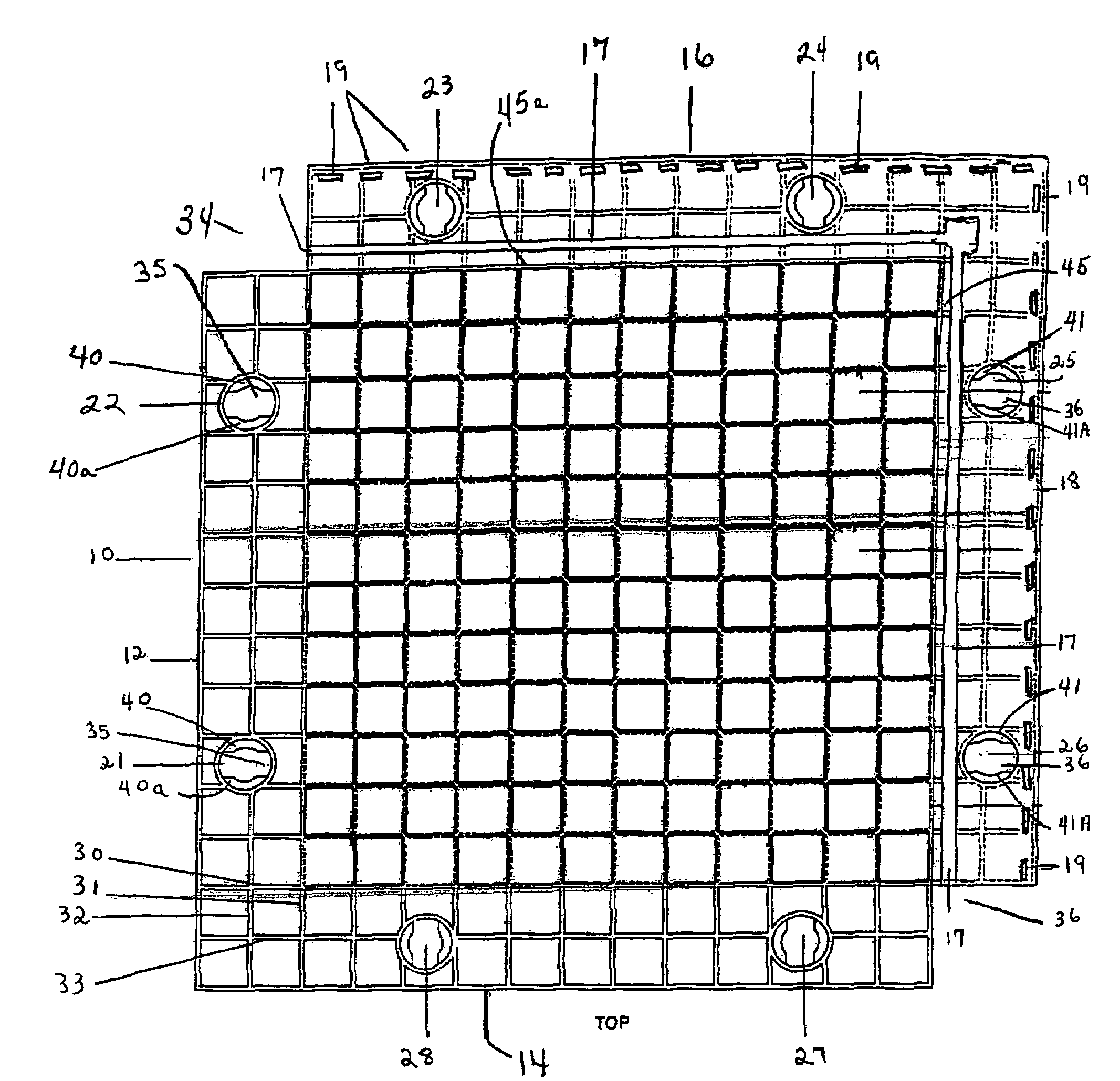
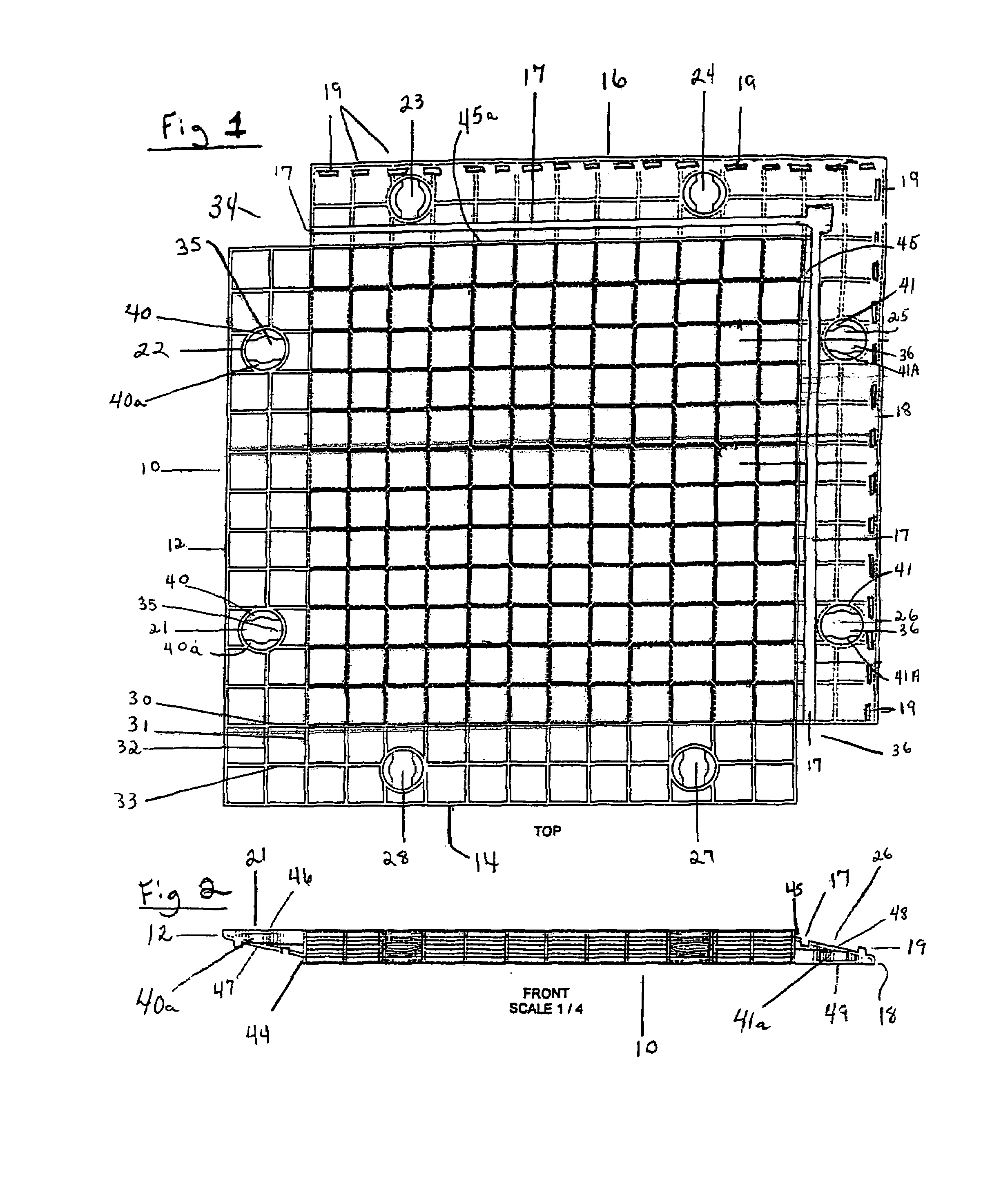
[0032]The present invention relates to an improved temporary load bearing structure having a collection of rigid mats with overlapping recessed lips to be fitted together to form a continuous flat interlocking load bearing surface. In FIG. 1, each mat 10 is made of rigid material preferably rigid polymeric plastic materials, rubber or any other moldable and / or castable material. The mat preferably is sized approximately 4′×4′ in length and width, approximately 2½ to 3 inches in height and weighs approximately 50 lbs to 60 lbs. Mat 10 is preferably made from well-known one piece injection molding manufacturing process and is shown with an interior cellular structure formed by vertical walls within the mat with the walls of one cell indicated by 30, 30a, 30b and 30c. The interior of mat 10 can be of solid construction or separate inserts of material can fill some or all the cells for greater load bearing strength. The insert material can be any compatible material and is preferably th...


PUM

PropertyMeasurementUnit
heightaaaaaaaaaa
angleaaaaaaaaaa
perimeteraaaaaaaaaa

Abstract

An mat system with each mat having sloping lips which overlap with an adjacent mat's sloping lips and are secured by interlocking joints in the mats' lips and/or by captive locking pins to form an easily assembled and interconnected flat surface. In use, opposing ledges forms a slot within holes in the top overlapping lips to receive a captive locking pin. The pin is captive by mid body prongs which fix underneath the ledges in a mat's upper lip's holes, and the pin locks and unlocks with rotary turning of the pin resulting in the pin's keeper feet fixing underneath the similar ledges in the holes of the lower lip of an adjacent mat.

Description

CROSS REFERENCE[0001]The present application is based on Provisional Application, Ser. No. 60,366,729, filed Mar. 22, 2002.BACKGROUND[0002]1. Field of the Invention[0003]The present invention relates to portable interlocking mats to be used as structural supports by persons or equipment. With multiple mats fastened together, the interlocking mats can be used to provide temporary structural support for a variety of uses, including, but not limited to, building floors, walkways and other uses.[0004]2. Description of Related Art[0005]Mats, utilized in a variety of embodiments, have long been used for the construction of temporary support surfaces. A few examples of patents that disclose various mat systems are as follows:[0006]U.S. Pat. No. 6,214,428B1(A laminated wooden support mat fitted with one or more wear mat or pad and are bolted together);[0007]U.S. Pat. No. 4,289,420 (A wooden mat to form a roadway from interlocking mats, each mat being formed from a plurality of layers or boa...

Claims


Application Information

Patent Timeline
Patent Type & Authority Patents(United States)
IPC IPC(8): B32B3/10B32B3/02B60N3/04B60R13/01E01C5/00E01C5/20E01C9/08E04F15/10F16B5/00F16B5/06F16B21/02
CPCB32B3/02E01C5/005E01C5/20E01C9/086E04F15/10F16B5/0635F16B21/02B60N3/046Y10T428/24017B60R13/01E01C2201/12E04F2201/05E04F2203/06F16B5/0004Y10T428/16Y10T428/169Y10T428/24008E04F15/02172E04F15/02194E04F15/06E04F15/105Y02A30/60
Inventor ROGERS, D. SCOTT
Owner SOLOCO LLC
Why Eureka
Try Eureka