DC/DC converter

a dc/dc converter and converter technology, applied in the field of dc/dc converters, can solve the problems of reducing the operation efficiency and the weight core has been a significant hindrance to the reduction of so as to reduce the overall size and weight of the dc/dc converter, reduce the size and weight of the coil section, and simplify the construction of the dc/dc converter.

Active Publication Date: 2007-12-04
HONDA MOTOR CO LTD
View PDF9 Cites 8 Cited by
  • Summary
  • Abstract
  • Description
  • Claims
  • Application Information

AI Technical Summary

Benefits of technology

[0008]In view of the foregoing prior art problems, it is an object of the present invention to provide an improved DC / DC converter which permits reduction in size and weight of its inductor, and which can increase its voltage boosting ratio to two or more, can continuously vary the voltage boosting ratio and voltage lowering ratio within a range of one to N times.
[0021]Namely, the DC / DC converter according to the present invention is characterized by employing: a transformer including primary and secondary windings of an opposite-winding configuration; an inductor provided at a state preceding the transformer; and switching elements for controlling energization of the primary and secondary windings. The inductor may be dispensed with to simplify the construction of the DC / DC converter. Such arrangements can reduce the size and weight of the coil section and thereby reduce the overall size and weight of the DC / DC converter. Where the present invention is constructed as a voltage-boosting DC / DC converter, the voltage-boosting ratio can be varied continuously. Further, the present invention can also be constructed as a voltage-lowering DC / DC converter, in which case too the voltage-lowering ratio can be varied continuously. Further, in the case where the transformer employs an intermediate tap between the primary and secondary windings, there can be achieved other benefits than the afore-mentioned that the voltage-boosting ratio etc. can be increased to N times equal to or greater than two times and can be varied in a continuous manner.

Problems solved by technology

In addition, the voltage-boosting DC / DC converter would present the inconvenience that the operating efficiency lowers as the voltage boosting ratio is increased.
Such a great-size, great-weight core has been a significant hindrance to reduction in the overall size and weight of the DC / DC converter.

Method used


Image

  • DC/DC converter
  • DC/DC converter
  • DC/DC converter

Examples


first embodiment

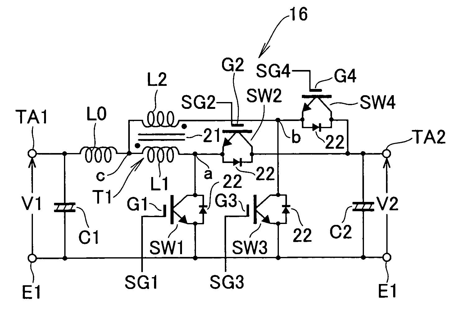
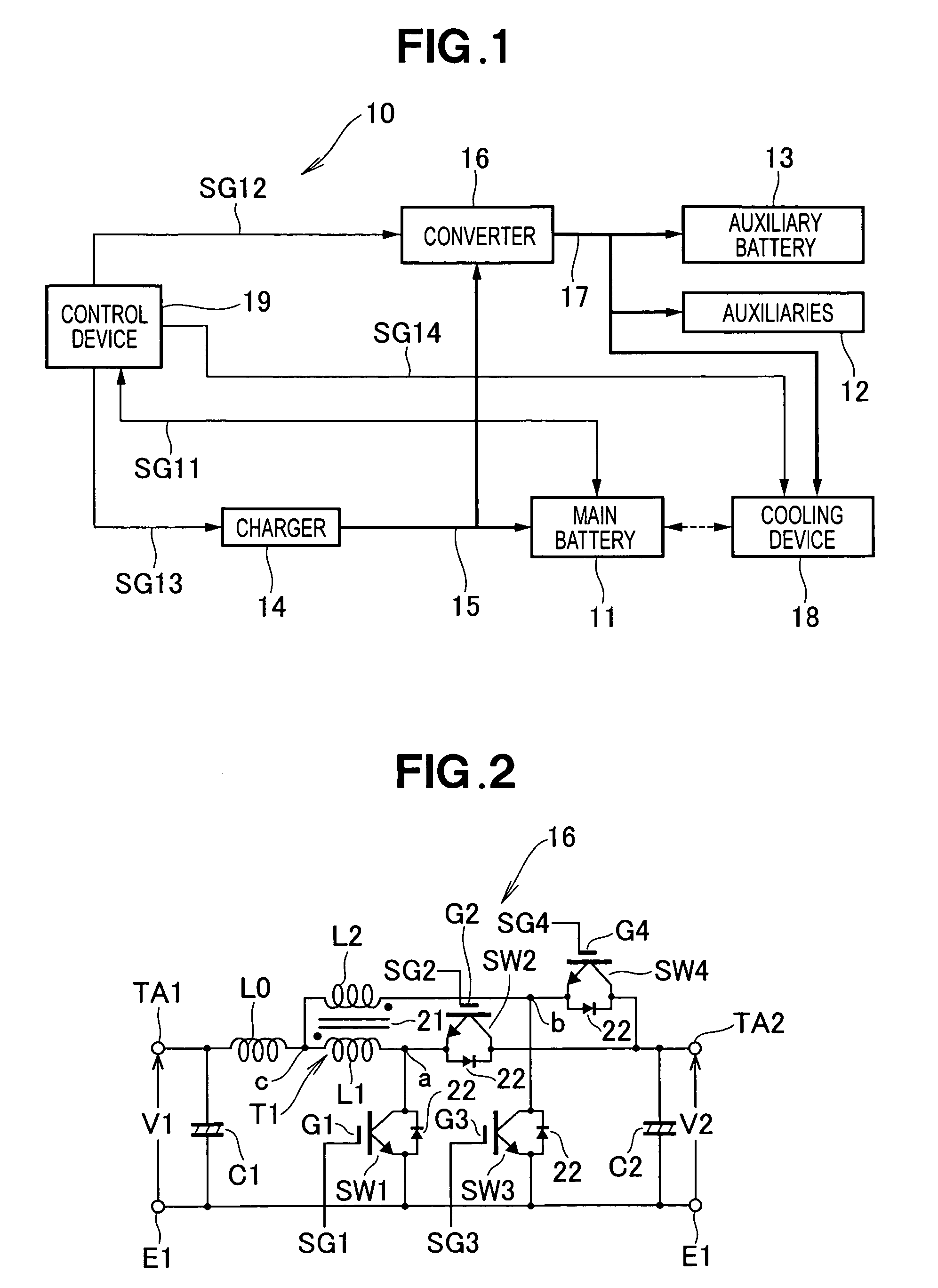
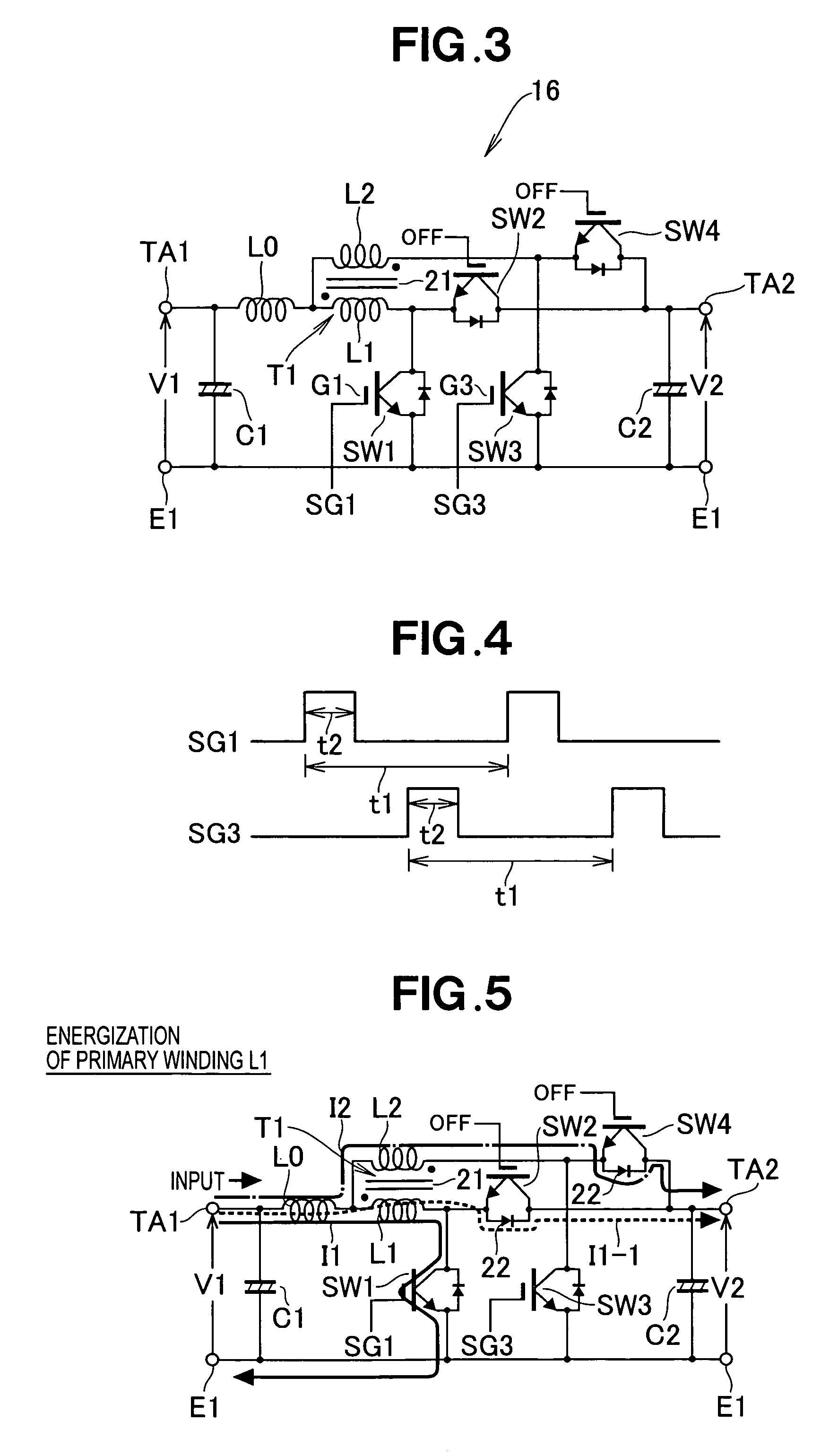
[0089]Similarly to the first embodiment, the DC / DC converter 31 includes a smoothing capacitor C1, an inductor (coil) L0, a transformer T1, four switching elements SW1, SW2, SW3 and SW4 and a smoothing capacitor C2. The DC / DC converter 31 also includes two diodes 32 and 33. DC voltage V1 is input to a positive-pole terminal TA1 of the low-voltage-side input port, and a DC voltage V2 is output from a positive-pole terminal TA2 of the high-voltage-side output port. Reference character E1 represents a common reference terminal (ground terminal).

second embodiment

[0090]The transformer T1 includes a core 21, and primary and secondary windings L1 and L2. The primary and secondary windings L1 and L2 are connected with each other and wound in opposite winding directions (i.e., interconnected in an “oppositely-wound configuration”). Winding ratio between the primary winding L1 and the secondary winding L2 is preferably 1:1. In the second embodiment, the primary and secondary windings L1 and L2 include intermediate taps 34 and 35, respectively. As shown in FIG. 16, the intermediate tap 34 divides the primary winding L1 with a winding ratio of n1:n2. With the winding ratio of n1:n2, a voltage-boosting ratio N of the voltage-boosting DC / DC converter 31 can be determined by

N=(n1+n2) / n1+1

The winding division ratio is determined in accordance with voltage-boosting / lowering requirements of a system to which is applied the present invention.

[0091]In the DC / DC converter 31, the inductor L0 is connected at one terminal to the terminal TA1, and a common ter...

third embodiment

[0109]the DC / DC converter 41 is constructed to perform voltage-boosting operation. In the voltage-boosting operation, the DC voltage V1 input to the low-voltage-side input port is boosted to the DC voltage V2 at the high-voltage-side input port.

[0110]Similarly to the second embodiment, the DC / DC converter 41 includes a smoothing capacitor C1, an inductor (coil) L0, a transformer T1, two switching elements SW1 and SW3, a smoothing capacitor C2, and two diodes 32 and 33. In the third embodiment, the switching elements SW2 and SW4 employed in the second embodiment are omitted and replaced with diodes 42 and 43. The DC voltage V1 is input to the positive-pole terminal TA1 of the low-voltage-side input port, and the DC voltage V2 (>V1) is output to the positive-pole terminal TA2 of the high-voltage-side output port. Reference character E1 represents a common reference terminal (ground terminal).

[0111]In the DC / DC converter 41, the diode 42 is connected between the intermediate tap 34 of ...


PUM


Abstract

Voltage-boosting / lowering DC / DC converter includes a low-voltage-side port and high-voltage-side port, an inductor connected at one end to a positive-pole terminal of the low-voltage-side port, and a transformer of a magnetic-field cancellation type including a primary winding and secondary winding interconnected in an oppositely-wound configuration, a common terminal of the primary winding and secondary winding being connected to the end of the inductor. Switching element controls an energizing current of the primary winding flowing to a common reference terminal, another switching element controls an energizing current of the primary winding flowing to a positive-pole terminal of the high-voltage-side port, still another switching controls an energizing current of the secondary winding flowing to the common reference terminal, and still another switching element controls an energizing current of the secondary winding flowing to the positive-pole terminal of the high-voltage-side port.

Description

FIELD OF THE INVENTION[0001]The present invention relates generally to DC / DC converters, and more particularly to an improved DC / DC converter which is suitable for use in power supply sections of electric vehicles etc. and which can also be suitably reduced in size and weight.BACKGROUND OF THE INVENTION[0002]Heretofore, there have been proposed various voltage-boosting DC / DC converters (for example, Japanese Patent Laid-Open Publication Nos. 2003-111390 and 2003-216255). FIG. 32 hereof shows a fundamental circuit structure in the conventional voltage-boosting DC / DC converter disclosed in one of the above-identified publications. The voltage-boosting DC / DC converter shown in FIG. 32 is in the form of electric circuitry capable of variable voltage boosting. This voltage-boosting DC / DC converter 100 is constructed using a single coil (i.e., inductor or inductance element) 101.[0003]More specifically, the DC / DC converter 100 of FIG. 32 includes an input-side smoothing capacitor 102, the...

Claims


Application Information

Patent Timeline
Patent Type & Authority Patents(United States)
IPC IPC(8): G05F1/40
CPCH02M3/1582H02M3/1588H02M3/1584Y02B70/1466Y02B70/10
Inventor WATANABE, YASUTOHIRAKAWA, MITSUAKI
Owner HONDA MOTOR CO LTD
Why Eureka
Try Eureka