Pseudodynamic off-chip driver calibration

a technology of driver calibration and off-chip driver, which is applied in the direction of logic circuits, pulse techniques, reliability increasing modifications, etc., can solve the problems of undesirable distortion of the slew rate disadvantageous matching of the off-chip driver, etc., and achieve good operating behavior

Active Publication Date: 2007-12-04
POLARIS INNOVATIONS LTD
View PDF8 Cites 6 Cited by
  • Summary
  • Abstract
  • Description
  • Claims
  • Application Information

AI Technical Summary

Benefits of technology

[0039]With individual calibration of the impedance value of each amplifying element, and improved linearization of the amplifying elements over their respective operating range, this calibration is referred to as pseudodynamic calibration.
[0042]For respective operating points to differ from the mid-value of the supply voltages by at most, for example, 35% of the difference between the supply voltages is a beneficial restriction on the individuality of the calibration and provides good operating behavior of the amplifying elements in an operating range which extends to the mid-value between the supply voltages.

Problems solved by technology

Such matching of the off-chip driver has been found to be disadvantageous in many applications, inter alia as an interface between DDR memory modules (DDR=“double-data-rate”) and corresponding external circuits.
In particular, an off-chip driver that has been matched in this way exhibits undesirable distortion of the slew rate and thus of the operating cycle in a circuit combination such as this.

Method used


Image

  • Pseudodynamic off-chip driver calibration
  • Pseudodynamic off-chip driver calibration
  • Pseudodynamic off-chip driver calibration

Examples


Embodiment Construction

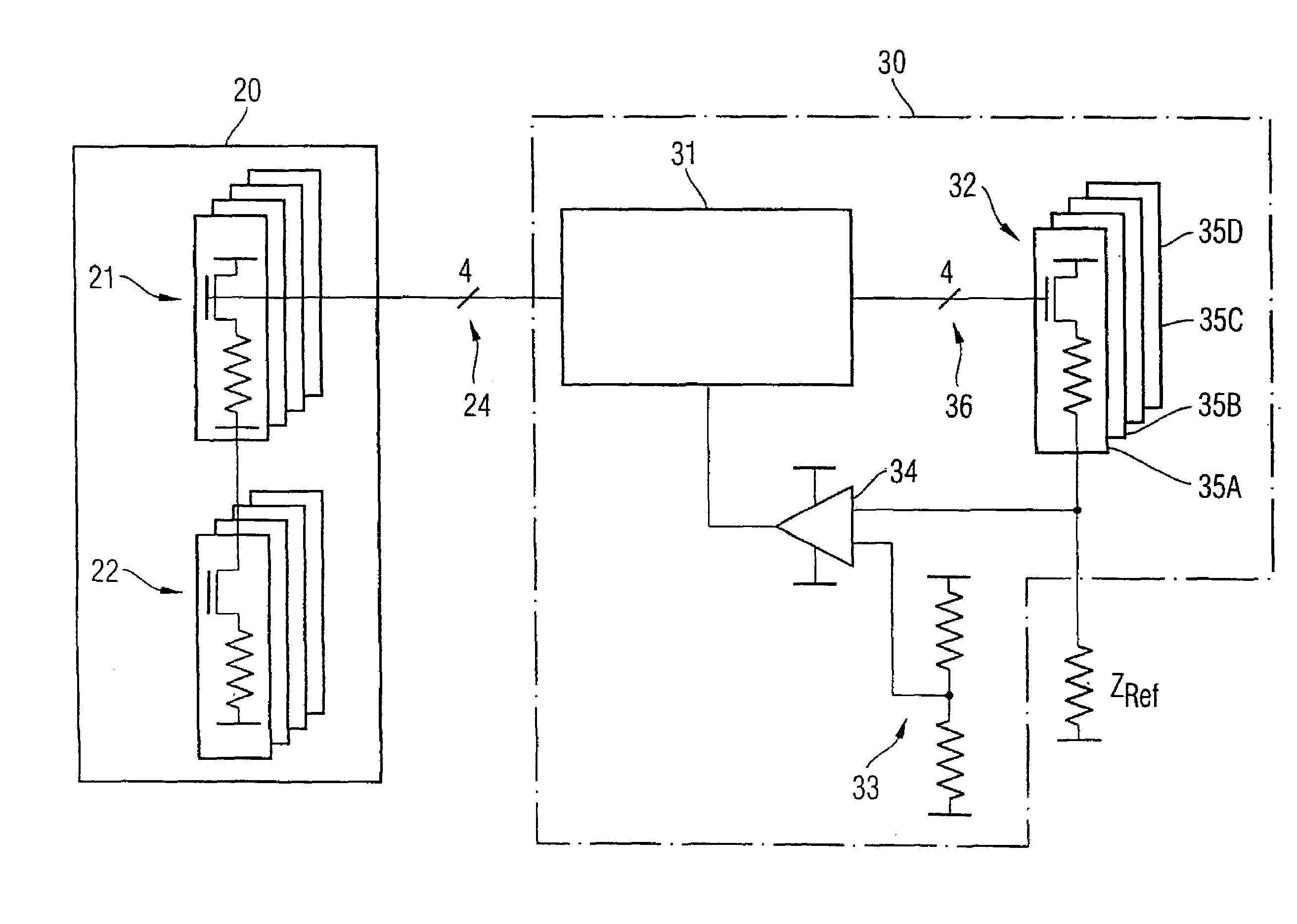
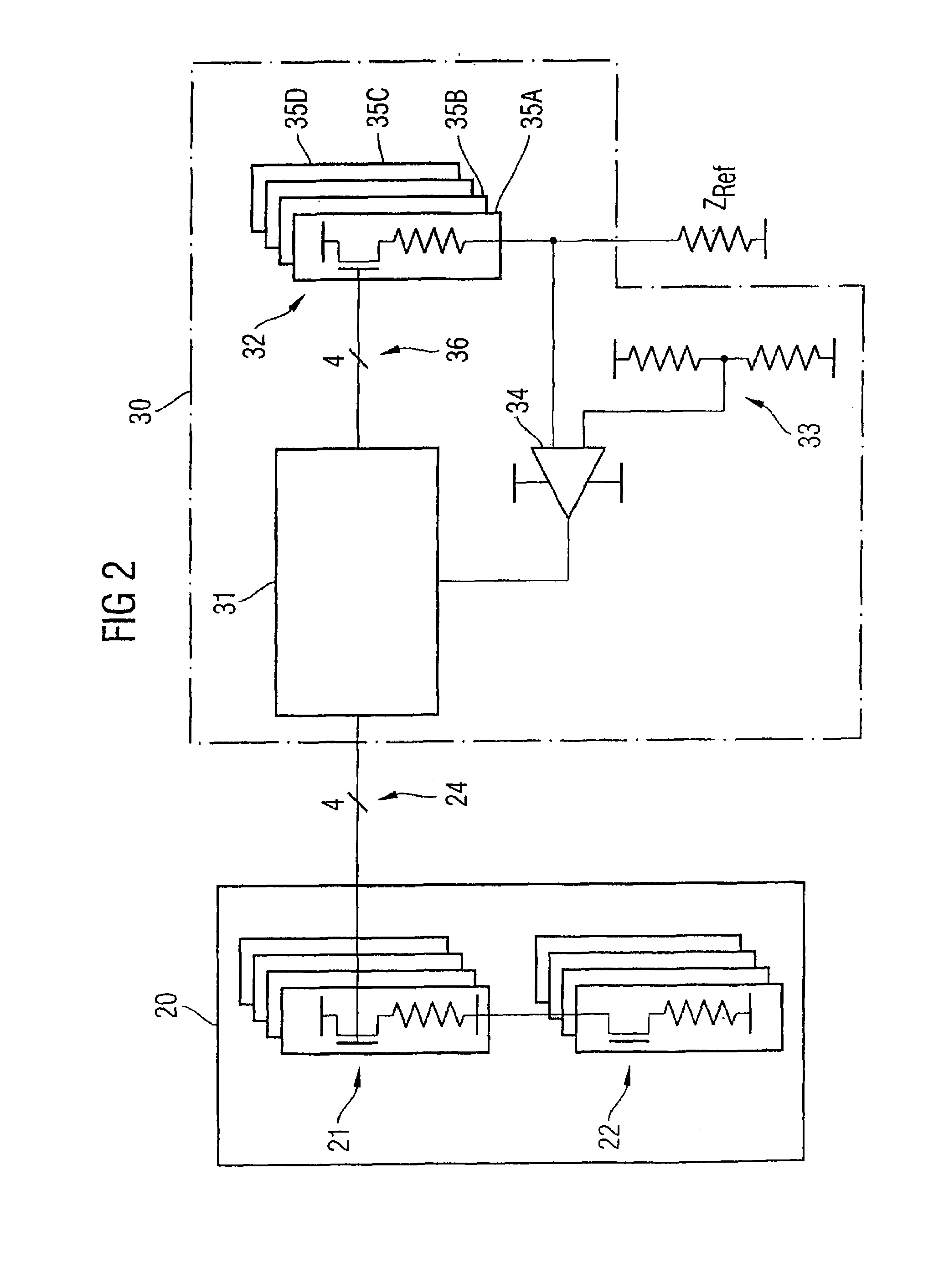
[0053]FIG. 2 shows a driver calibration circuit arrangement 30 according to a first exemplary embodiment of the invention, together with a driver circuit arrangement 20, illustrated schematically. The illustration shows a driver calibration circuit arrangement 30, which has a monitoring device 31, a variable impedance 32, a reference voltage divider 33, a comparator 34, and control lines 36. The driver calibration circuit arrangement 30 is connected to a reference impedance ZRef and to the driver circuit arrangement 20. The latter connection is made via a control line 24 which, for example, has four conductors. The variable impedance 32 comprises two or more switchable impedances 35A-D, which can be switched on and off via the control lines 36. The driver circuit arrangement 20 has a pull-up branch 21 and a pull-down branch 22, whose respective impedance can be influenced via the control line 24.

[0054]Together with the reference impedance ZRef, the variable impedance 32 forms a volt...


PUM


Abstract

A driver system, a driver calibration circuit arrangement for calibration of an impedance of a driver circuit arrangement, and a method for calibration of an impedance of a driver circuit arrangement can achieve improved driver behavior, with respect to undesirable distortions of the slew rate caused by off-chip drivers of DDR memory modules. A driver system has a first driver part with at least one variable impedance by which an operating point of the first driver part is determined with respect to a first potential and a second potential. The potentials supply the first driver part. A first monitoring device adjusts an impedance value of the variable impedance such that the operating point differs from a mid-point of the first and of the second potential.

Description

CROSS REFERENCE TO RELATED APPLICATIONS[0001]This application claims priority under 35 USC § 119 to German Application No. DE 10351016.8, filed on Oct. 31, 2003, and titled “Pseudodynamic Off-Chip Driver Calibration,” the entire contents of which are hereby incorporated by reference.FIELD OF THE INVENTION[0002]The present invention relates to a driver system, a driver calibration circuit arrangement for calibration of an impedance of a driver circuit arrangement, and a method for calibration of an impedance of a driver circuit arrangement.BACKGROUND[0003]Off-chip drivers are known for carrying out various tasks. For example, off-chip drivers are used where a signal which has been produced within a chip, i.e., within an integrated semiconductor circuit (also referred to as a module) is intended to be amplified before being transmitted to a circuit, which is external to the chip. The signal power or the signal level of the signal, which is produced on the chip, can be matched to the r...

Claims


Application Information

Patent Timeline
Patent Type & Authority Patents(United States)
IPC IPC(8): H03K17/16H03K19/00
CPCH03K19/0005
Inventor NYGREN, AARON
Owner POLARIS INNOVATIONS LTD
Why Eureka
Try Eureka