Digital phase detector improving phase detection resolution thereof

a digital phase detector and resolution technology, applied in oscillation comparator circuits, automatic control of pulses, instruments, etc., can solve the problems of reducing phase margin, difficult to reduce the response time of the pll circuit, and inability to take advantage of the recent digital cmos miniaturization. to achieve the effect of improving the phase detection resolution

Active Publication Date: 2007-12-04
SOCIONEXT INC
View PDF12 Cites 40 Cited by
  • Summary
  • Abstract
  • Description
  • Claims
  • Application Information

AI Technical Summary

Benefits of technology

[0011]An object of the present invention is to provide a digital phase detector improving the phase detection resolution thereof.

Problems solved by technology

An analog PLL circuit such as described above uses analog devices such as a capacitive device and a resistive device, but since such analog devices cannot be fabricated using a standard digital CMOS process, different options are often needed.
Furthermore, in cases where these analog devices become a dominant factor in determining the area that the PLL circuit occupies, the benefits of the recent digital CMOS miniaturization cannot be taken advantage of.
Moreover, the analog configuration has two or more poles in the loop of the PLL circuit; therefore, if the bandwidth of the loop is set wide, the phase margin is reduced and, as a result, it becomes difficult to reduce the response time of the PLL circuit.

Method used


Image

  • Digital phase detector improving phase detection resolution thereof
  • Digital phase detector improving phase detection resolution thereof
  • Digital phase detector improving phase detection resolution thereof

Examples


Embodiment Construction

[0022]Before describing in detail the preferred embodiments of a digital phase detector according to the present invention, a conventional digital phase detector and its associated problems will be described with reference to FIGS. 1 and 2.

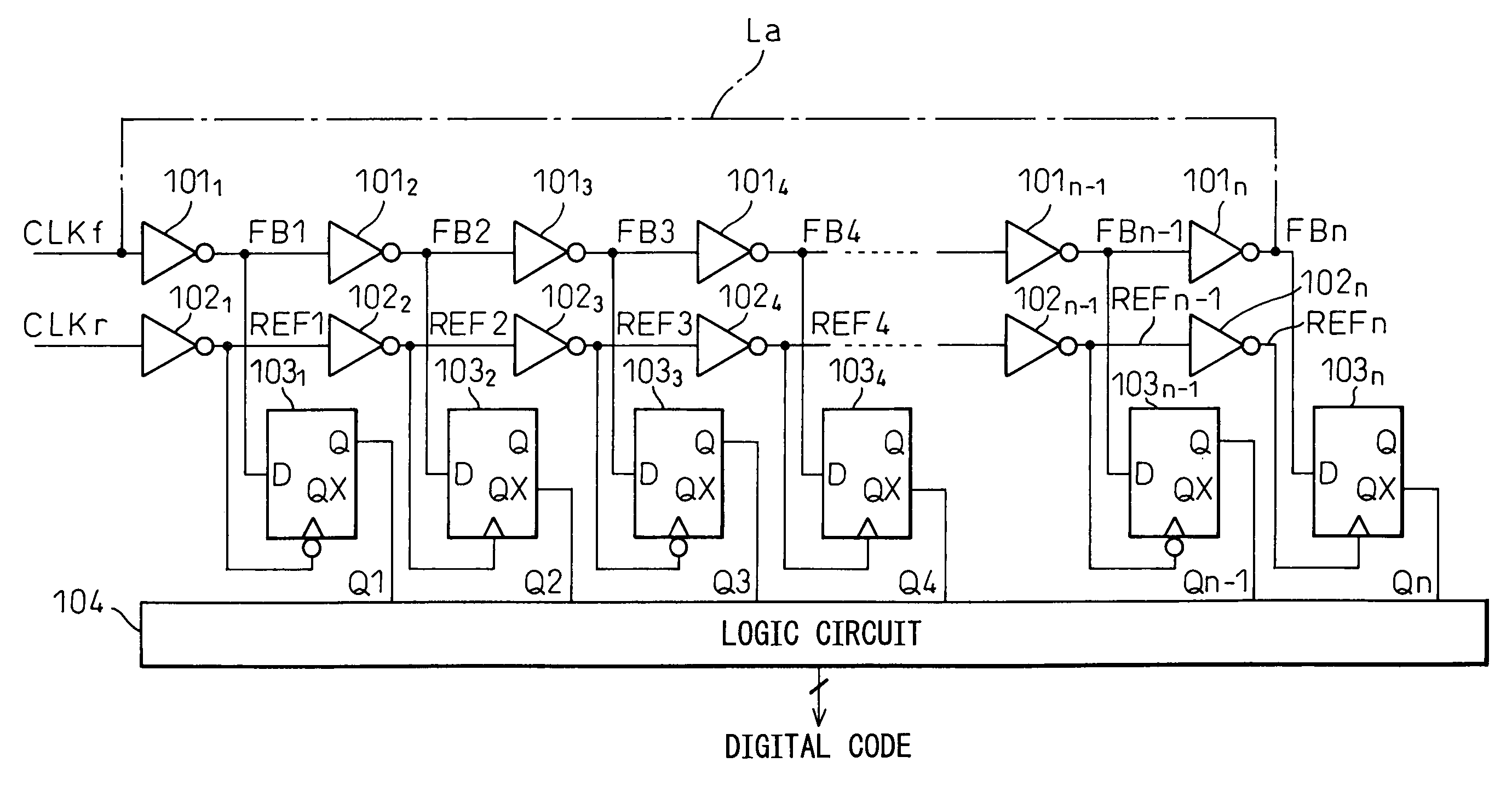
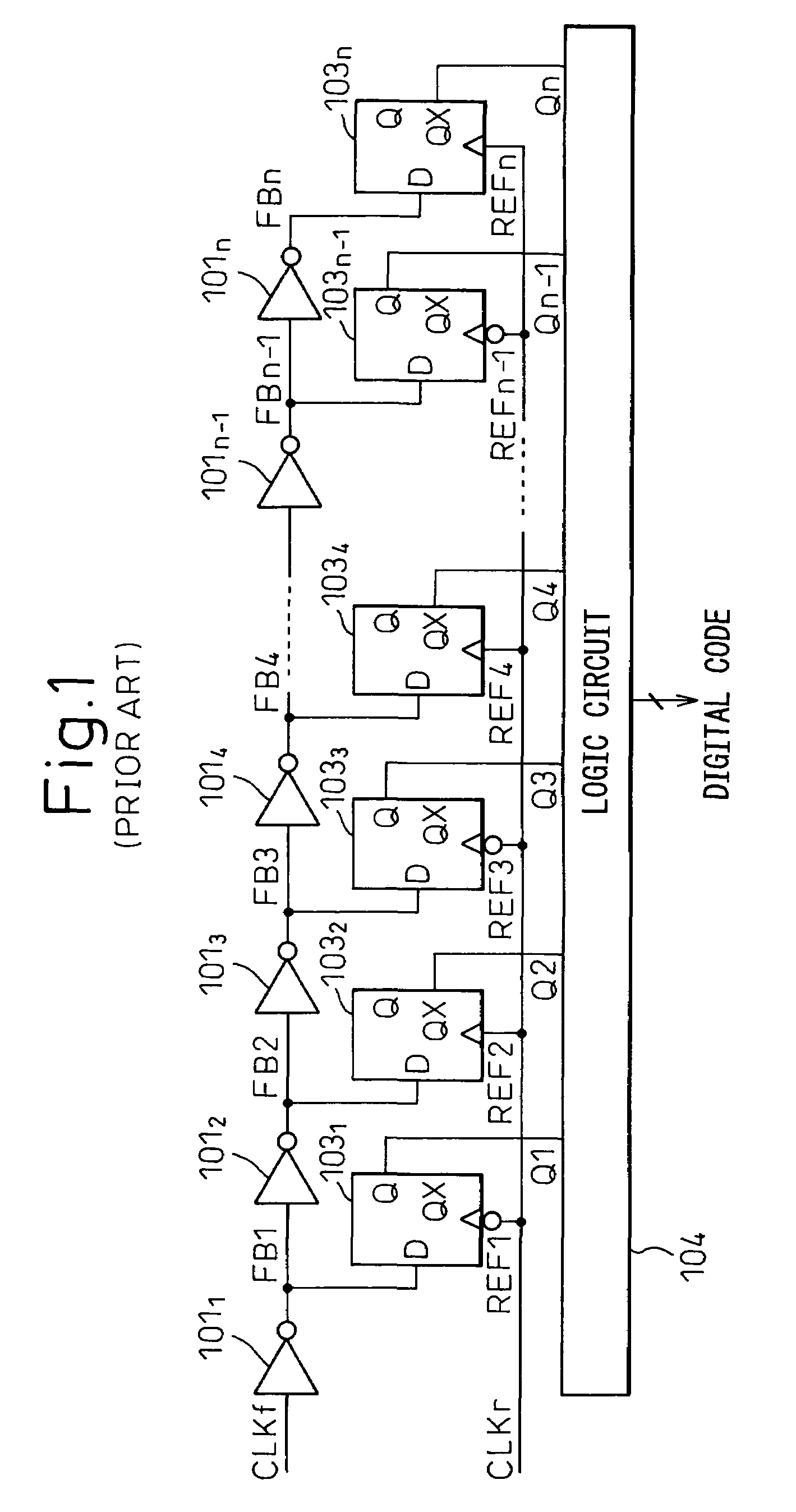
[0023]FIG. 1 is a block circuit diagram schematically showing one example of the prior art digital phase detector. In FIG. 1, reference numerals 1011 to 101n are delay elements (inverters), 1031 to 103n are data holding circuits (flip-flops), 104 is a logic circuit, CLKf is a feedback clock, and CLKr is a reference clock.

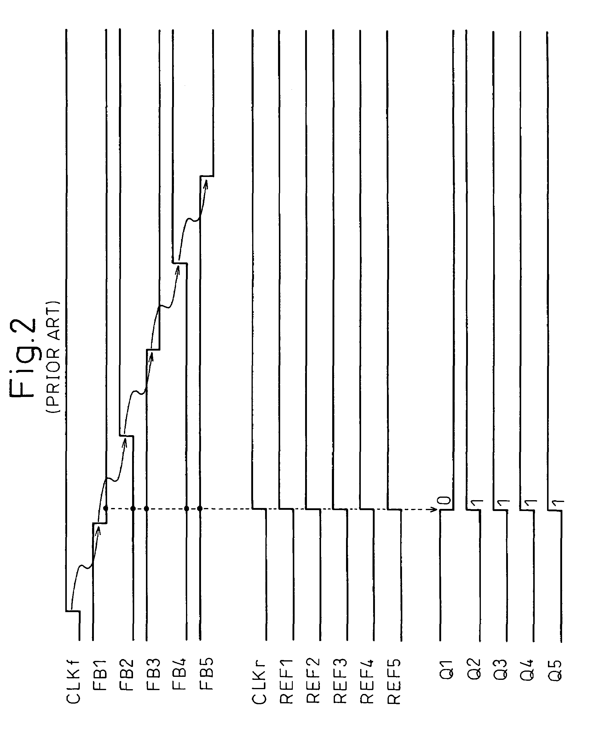
[0024]As shown in FIG. 1, in the prior art digital phase detector, the feedback clock CLKf is passed through the plurality of delay elements 1011 to 101n to generate feedback clocks (clocks FB1 to FBn) successively delayed by the delay time of each of the delay elements 1011 to 101n, thereby successively changing the phase relationship relative to the reference clock CLKr (clocks REF1 to REFn). Here, each of the delay elements 101...


PUM


Abstract

A digital phase detector has a plurality of first delay elements through which a first clock is delayed, a plurality of second delay elements through which a second clock is delayed, and a plurality of data holding circuits. The data holding circuits latch the first clock successively delayed through the first delay elements and hold a digital value representing a relative phase difference, in accordance with the second clock successively delayed through the second delay elements. Therefore, the phase detection resolution of the digital phase detector can be improved.

Description

CROSS REFERENCE TO RELATED APPLICATION[0001]This application is based upon and claims the benefit of priority from the prior Japanese Patent Application No. 2005-298491, filed on Oct. 13, 2005, the entire contents of which are incorporated herein by reference.BACKGROUND OF THE INVENTION[0002]1. Field of the Invention[0003]The present invention relates to a digital phase detector and, more particularly, to a digital phase detector which is fabricated in a standard digital CMOS process and is used as a phase comparator in a Phase-Locked Loop (PLL) circuit.[0004]2. Description of the Related Art[0005]In a conventional analog PLL circuit, phase difference information from a phase comparator is given in the form of an output pulse width, and a charge pump circuit supplies a charge proportional to the pulse width to a control voltage terminal of a voltage-controlled oscillator (VCO). A loop filter, to which the control voltage terminal is also connected, converts the charge supplied from ...

Claims


Application Information

Patent Timeline
Patent Type & Authority Patents(United States)
IPC IPC(8): G01R25/00
CPCH03D13/004H03L7/113H03L7/091H03L7/087
Inventor MATSUTA, HIROTO
Owner SOCIONEXT INC
Why Eureka
Try Eureka