Zoom lens unit, imaging device and photographing device

a zoom lens and imaging device technology, applied in the field of zoom lens units, imaging devices and photographing devices, can solve the problems of difficult to tolerate ghost images, no specific data about the zoom lens units themselves, and measures against ghost images, so as to effectively inhibit ghost images

Active Publication Date: 2007-12-04
RICOH KK
View PDF29 Cites 17 Cited by
  • Summary
  • Abstract
  • Description
  • Claims
  • Application Information

AI Technical Summary

Benefits of technology

[0013]An object of the present invention is to effectively inhibit a ghost image caused by reflection between lens surface to lens surface of a first and a second lens groups located nearer to an object side than an aperture stop in a zoom lens unit.

Problems solved by technology

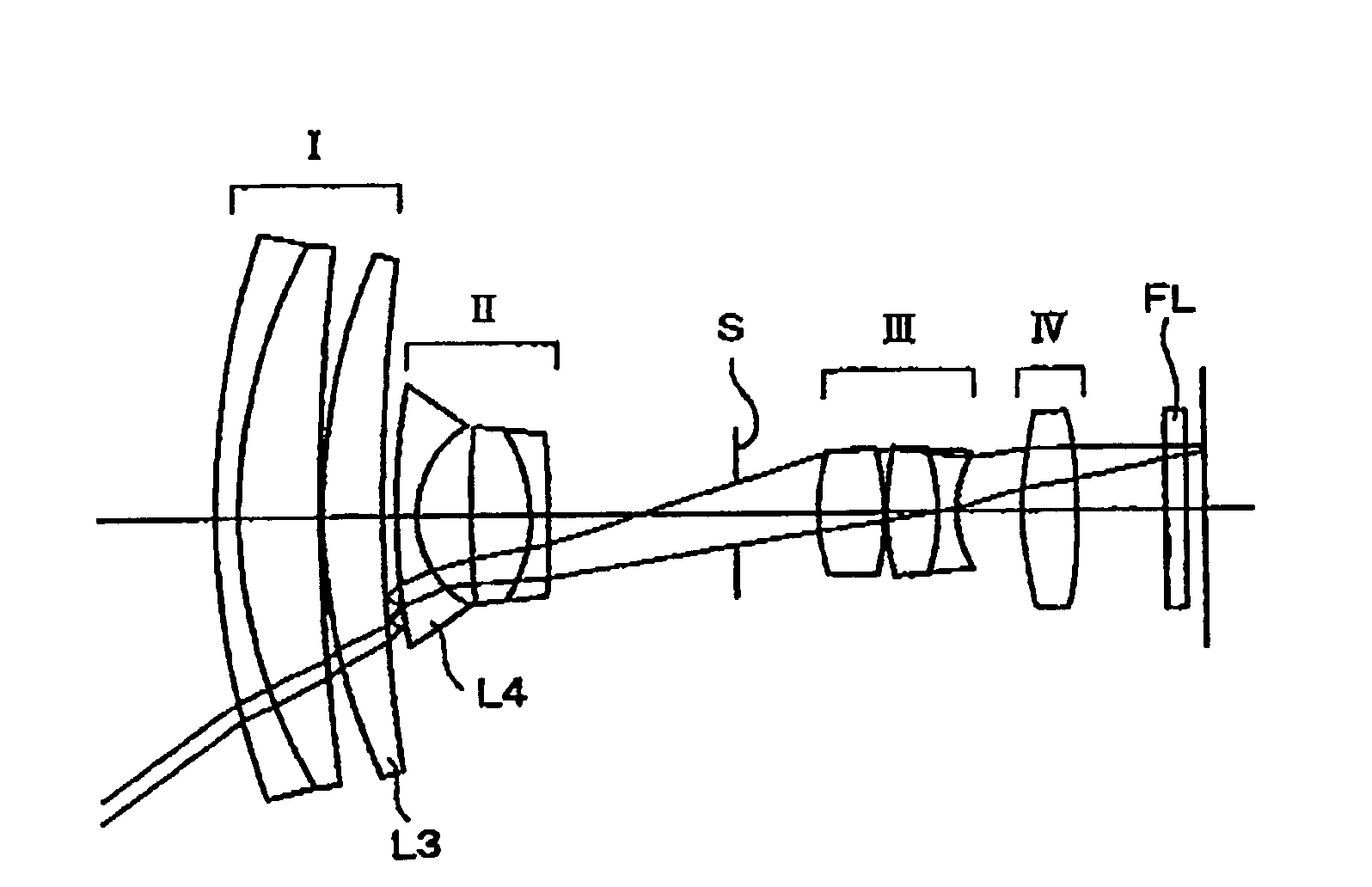
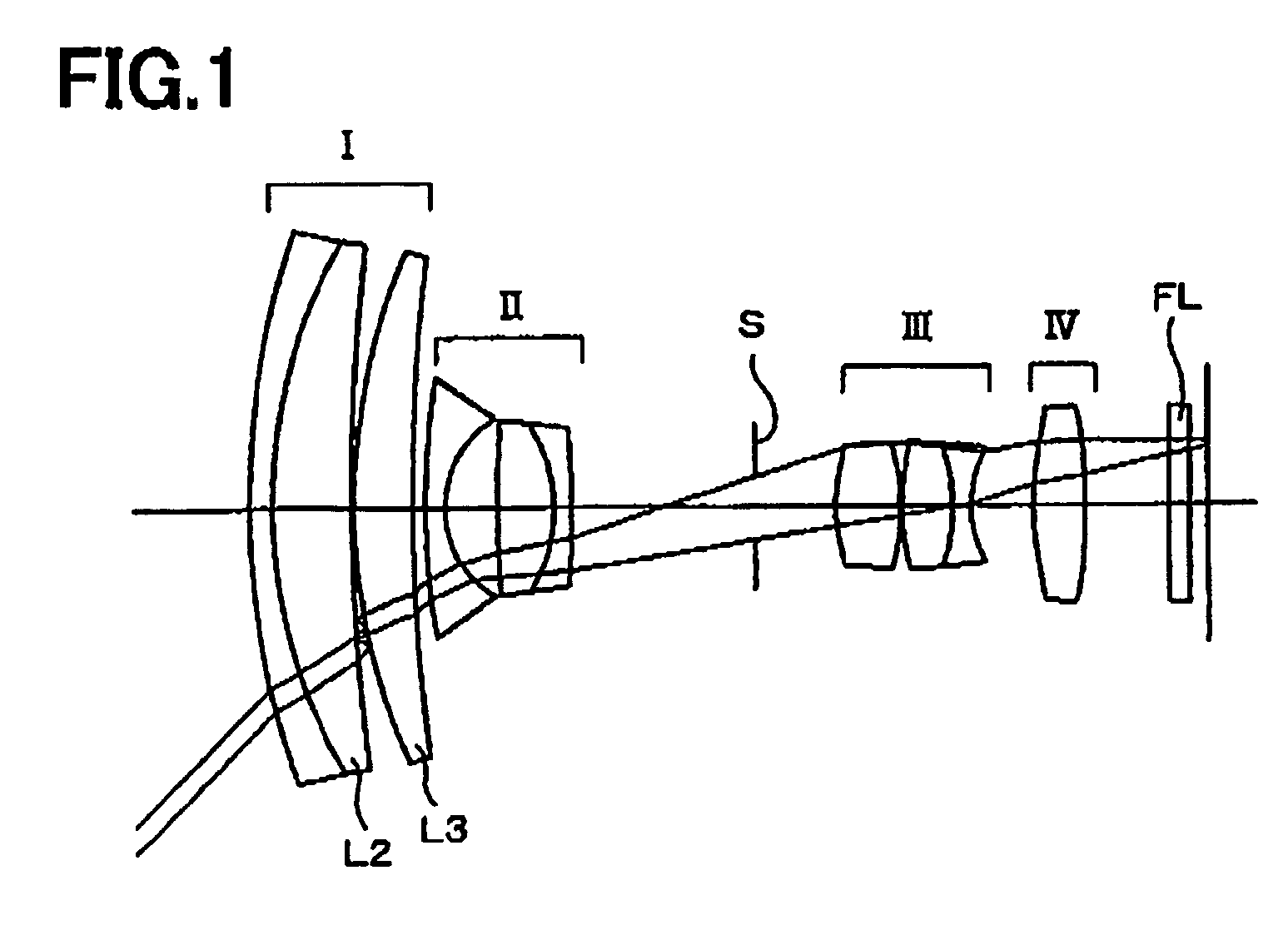
Since in general the zoom lens unit is constructed by the large number of lenses, measures against the ghost image are an important technological issue.
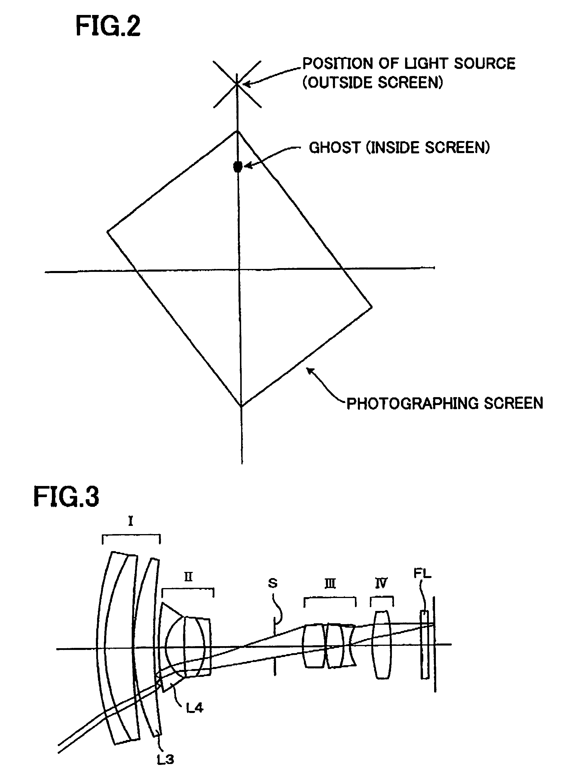
In the case that the strong light source exists in the photographing screen, the ghost image is easily tolerated because it is not so distinguished, as compared with an image of the strong light source, while in the case that the light source is outside of the photographing screen, the ghost image is difficult to be tolerated since it is apt to be distinguished.
However, there is no specific data about the zoom lens unit itself, and the magnification ratio and the half field angle at the wide angle end are uncertain.
For example, a blue ghost image and a yellow ghost image on the short wavelength side are relatively not obvious, so that they are easy to be tolerated, while a red ghost image is obvious and therefore it is hard to be tolerated.
Therefore, it becomes difficult to correct the entire aberrations.
If the entire length at the telephoto end becomes too long, not only the reduction of the size in the entire length direction is disturbed, but also the radial direction grows in size for securing the light volume around at the telephoto end, and the image performance is also easily deteriorated by the manufacturing error such as the falling of lens barrel.
If Y′max / fW becomes larger than 1.00, it is undesirable since that it is difficult to secure the image performance in the neighbouring part and the lens increases in size.
However, the large refracting power is required for each lens in the first lens group, and the negative effect such as the deterioration in the chromatic aberration especially at the telephoto end is easily produced.
In addition, each lens in the first lens group is increased in the thickness and diameter, and it is disadvantageous to the reduction of the size in a collapsed state.
If the parameter of the condition (7), f1 / fW becomes larger than 12.0, the contribution to the changing magnification of the second lens group is reduced, and it becomes difficult to obtain the larger changing magnification.
Also, it becomes disadvantageous with regard to the ensuring of off-axis performance because the aberration in the changing magnification area is hardly balanced.
Especially, it becomes difficult to secure the performance at the wide field angle.
If the distance between the aperture stop and the third lens group becomes to be the widest except at the wide angle end, it becomes difficult to balance the off-axis aberration in the entire changing magnification area because the height of light passing the third lens group becomes to be the largest at the position.
In addition, if the distance between the aperture stop and the third lens group becomes to be the narrowest except at the telephoto end, the distance between the second lens group and the third lens group may not be sufficiently reduced at the telephoto end.
Thereby, it becomes difficult to correct the entire aberration because the contribution to the changing magnification of the third lens group is lowered.
If m4T is smaller than 0.60, the luminous flux emitting to the third lens group approaches afocal, and it is impossible for the third lens group to change the magnification effectively, and as a result, the share of changing magnification of the second lens group increases, and also it becomes difficult to correct the field curvature and astigmatism which increase with the wider field angle.
On the other hand, if m4T is larger than 0.85, a required back-focus may not be secured, or the refracting power of the fourth lens group becomes too small, because the fourth lens group is too close to the image side.
Therefore, the shortage of light volume in the neighboring portion is easily caused.
Accordingly, it becomes difficult to balance the image plane when changing the magnification.
On the other hand, if the parameter, m4T / m4W is larger than 1.3, it becomes difficult to correct the aberration with the simple structure of the fourth lens group comprising one positive lens because the share of changing magnification of the fourth lens group becomes too big.
Therefore, it becomes difficult to balance the axial chromatic aberration and magnification chromatic aberration over the entire zooming area.
In addition, when focusing to a finite distance object by moving the fourth lens group, the fluctuation of chromatic aberration by the focusing increases.
If v4 is larger than 75, it is advantageous to the correction of chromatic aberration, but the material is expensive and also it is difficult to process both surfaces as an aspheric surface.

Method used


Image

  • Zoom lens unit, imaging device and photographing device
  • Zoom lens unit, imaging device and photographing device
  • Zoom lens unit, imaging device and photographing device

Examples


Embodiment Construction

[0118]An embodiment of a photographing device will be described with reference to FIGS. 11A to 11 and 12. In this embodiment, the photographing device is a mobile information terminal, although it is not limited thereto.

[0119]As illustrated in FIGS. 11A to 11 and 12, a mobile information terminal 30 includes a photographing lens 31 and an area-type light receiving element (area sensor) 45 which is an imaging element. In the mobile information terminal 30, an image of a photographic object by the photographing lens 31 is imaged onto the light receiving element 45, and the image is read out by the light receiving element 45.

[0120]As the photographing lens 31, for example, any one of the zoom lenses described in (a)-(m), more particularly, a zoom lens unit described in the after-mentioned embodiment is used, for example. In addition, as the light receiving element 45, a light receiving element having 5 million to 8 million pixels or more, for example, a CCD (Charge-Coupled Device) area...


PUM

PropertyMeasurementUnit
reflectivityaaaaaaaaaa
half field angleaaaaaaaaaa

Abstract

A zoom lens unit includes: a positive first lens group; a negative second lens group; and a positive subsequent lens group as a whole, the subsequent lens group includes a third lens group, and an aperture stop is disposed between the second lens group and the third lens group, and a lens construction including the first and the second lens groups satisfies the condition (1): 1.0<ri / ri+1<5.0, in which ri and ri+1 are curvature radii of lens surfaces Si and Si+1 in the lens construction, respectively, the lens surfaces Si and Si+1 being “i”th and “i+1”th lens surfaces, respectively, counted from the object side, and a reflectivity-reducing treatment adapted to reduce intensity of a ghost image is performed on each lens surface forming at least one of pairs of lens surfaces satisfying the condition (1).

Description

BACKGROUND[0001]1. Field of the Invention[0002]The present invention relates to a zoom lens unit, an imaging device and a photographing device.[0003]2. Description of Related Art[0004]Such a zoom lens unit, which includes in order from an object side: a first lens group having a positive refracting power; a second lens group having a negative refracting power; and a subsequent lens group comprising one or more lens groups and having a positive refracting power as a whole, and an aperture stop disposed between the second lens group and the subsequent lens group, wherein when changing a modification from a wide angle end to a telephoto end, a distance between the first lens group and the second lens group increases, and a distance between the second lens group and the subsequent lens group decreases, is suitable for “miniaturization and high magnification ratio”, and is embodied widely for video camera and digital camera as the zoom lens unit therefor.[0005]The zoom lens unit with suc...

Claims


Application Information

Patent Timeline
Patent Type & Authority Patents(United States)
IPC IPC(8): G02B15/14G02B13/18G02B15/20
CPCG02B1/11G02B15/173G02B13/18G02B15/143105
Inventor OHASHI, KAZUYASU
Owner RICOH KK
Why Eureka
Try Eureka