Disk drive and detection method using pre-pit detection and push-pull signal generation

a detection method and pre-pit technology, applied in the direction of digital signal error detection/correction, instruments, recording signal processing, etc., can solve the problems of increasing the address error rate, difficult to correctly read the land pre-pits lpp, and recording marks (phase change bits) formed on the grooves

Inactive Publication Date: 2007-12-04
SONY CORP
View PDF19 Cites 27 Cited by
  • Summary
  • Abstract
  • Description
  • Claims
  • Application Information

AI Technical Summary

Benefits of technology

[0041]In view of the above, it is an object of the present invention to provide a disk drive capable of correctly detecting land pre-pit

Problems solved by technology

However, if information is written on grooves serving as recording tracks, recording marks (phase change bits) formed on the grooves interfere with the land pre-pits LPP.
As a result, it becomes difficult to correctly read the land pre-pits LPP.
Such a variation in level of the push-pull signal P/P can result in noise in the detection signal LPPout corresponding to land pre-pits detected by comparing the push-pull signal P/P with the reference voltage Vth.
Incorrect detection of land pre-pits LPP results in an increase in address error rate.
That is, it becomes impossible to correctly read address information.
This results in degradation in performance of operation of writing/reading data on/from a disk and also degradation in seeking operation.
However, the in

Method used


Image

  • Disk drive and detection method using pre-pit detection and push-pull signal generation
  • Disk drive and detection method using pre-pit detection and push-pull signal generation
  • Disk drive and detection method using pre-pit detection and push-pull signal generation

Examples


first embodiment

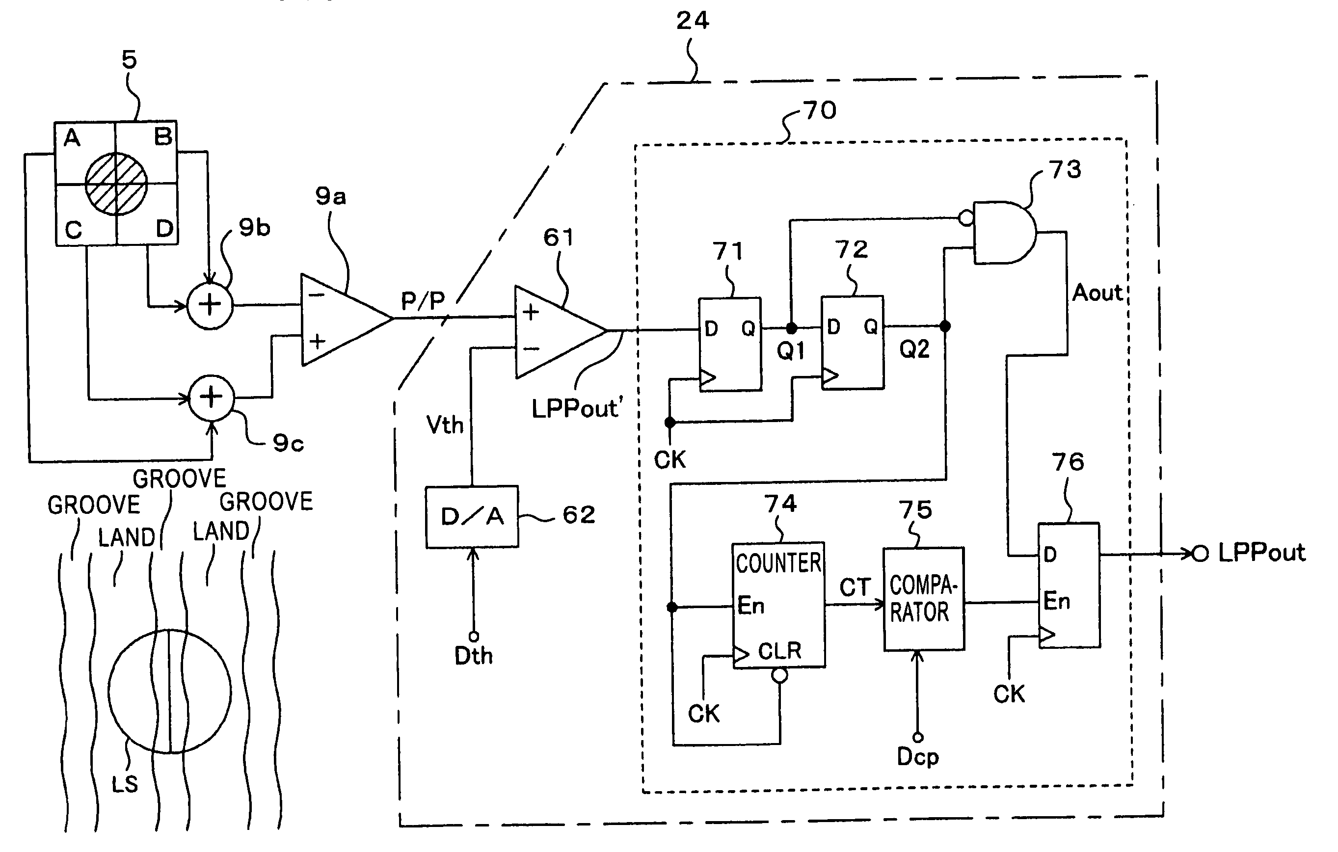
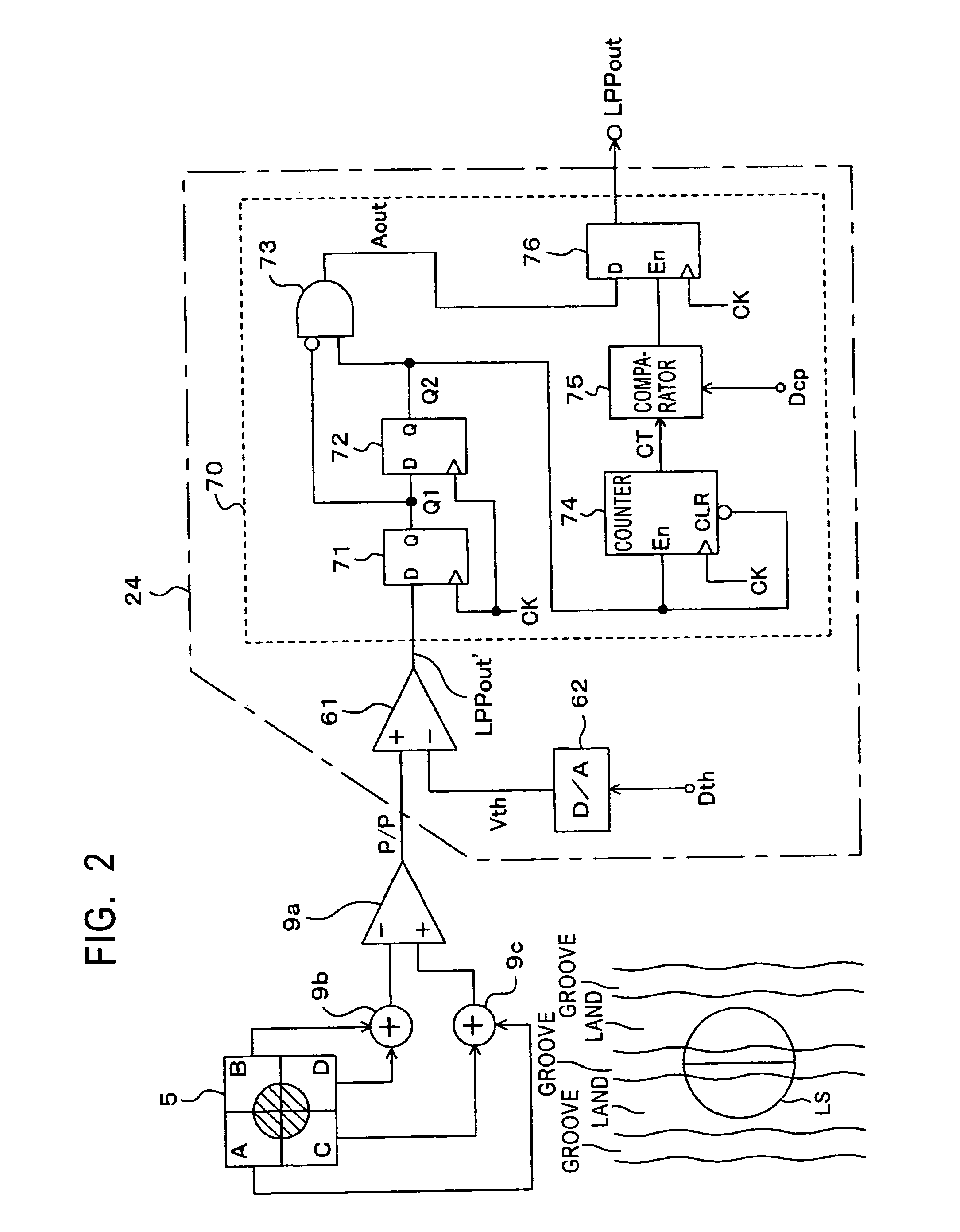
[0127]In the disk drive 30 described above, a specific circuit configuration for detecting land pre-pits formed on a disk and the operation of the circuit, according to a first embodiment, are described below with reference to FIGS. 2 and 3.

[0128]Of various parts of the disk drive 30, a part serving to detect land pre-pits is shown in FIG. 2. The part includes the photodetector 5 of the pickup 1, the adders 9b and 9c and the differential amplifier 9a of the matrix circuit 9, and the land pre-pit extractor 24.

[0129]Although not shown in FIG. 2, the matrix circuit 9 includes not only the differential amplifier 9a and the adders 9b and 9c for generating the push-pull signal P / P but also a circuit part for generating the RF signal, the focus error signal FE, and the tracking error signal TE.

[0130]As shown in FIG. 2, the photodetector 5 is of the quadrant type including four photodetector elements A, B, C, and D. Light reflected from a disk is detected by respective photodetector element...

second embodiment

[0166]Referring to FIG. 4, a circuit configuration including a noise pulse remover 70 according to a second embodiment is described below. The circuit configuration is similar to that according to the first embodiment described above except that the noise pulse remover 70 is configured in an analog form.

[0167]As shown in FIG. 4, the noise pulse remover 70 includes a resistor R1, a diode D1, a capacitor C1, a comparator 77, and a reference voltage source 78.

[0168]In this circuit configuration, a detection signal LPPout', which might include noise pulses, is supplied from a comparator 61 to the noise pulse remover 70. In the noise pulse remover 70, when the detection signal LPPout' is at a level of “1”, the capacitor C1 is charged up by the detection signal LPPout' at a rate corresponding to the time constant determined by the resistance R1.

[0169]The charged voltage of the capacitor C1 varies in a similar manner to the count value CT shown in FIG. 3(e) according to the first embodimen...

third embodiment

[0174]Referring to FIGS. 5 and 6, a circuit configuration including a noise pulse remover 70 according to a third embodiment is described below. The circuit configuration is similar to that according to the first embodiment described above except that the noise pulse remover 70 is formed using a shift register.

[0175]In this third embodiment, the noise pulse remover 70 includes a shift register composed of n flip-flops SR1 to SR(n) and a pulse length detector 79 to which latched signals are supplied from the respective flip-flops SR1 to SR(n).

[0176]In the pulse length detector 79, a set value CL is given by the system controller 10, and if outputs of as many or more flip-flops than the set value CL are “1”, the output of the pulse length detector 79 becomes “1”. The pulse length detector 79 may be realized, for example, using a multiinput AND gate.

[0177]FIG. 6 shows waveforms associated with the operation of the noise pulse remover 70.

[0178]Also in this noise pulse remover 70, as sho...


PUM


Abstract

A push pull signal is detected from a disk-shaped storage medium on which wobbling grooves are formed as recording tracks and address information is recorded by forming pre-pits on lands between adjacent grooves. The detected push-pull signal is compared with a reference voltage thereby generating a land pre-pit detection signal. Of pulses included in the land pre-pit detection signal, those pulses having a small pulse width are regarded as noise pulses and removed thereby obtaining a corrected land pre-pit detection signal. The number of pulses included in the land pre-pit detection signal is counted, and the reference voltage is controlled in accordance with the counted number of pulses.

Description

BACKGROUND OF THE INVENTION[0001]1. Field of the Invention[0002]The present invention relates to a disk drive for writing / reading data on / from a disk-shaped storage medium such as an optical disk and also to a method of detecting pre-pits.[0003]2. Description of the Related Art[0004]In order to write data on a disk, it is required that the disk has guide means for forming data tracks. To meet the above requirement, grooves serving as pre-grooves are formed and resultant grooves or lands (protrusions having the shape of plateau in cross section between adjacent grooves) are used as data tracks.[0005]In order to write data at a desired location on a data track, it is required that an address information be recorded on the disk. The address information is generally recorded by wobbling the grooves or by forming pre-pits on the data tracks.[0006]For example, in the case of DVD-RW that is a rewritable version of DVD (Digital Versatile Disc) based on the phase change recording or DVD-R th...

Claims


Application Information

Patent Timeline
IPC IPC(8): G11B7/00G11B7/004G11B20/10G11B7/005G11B7/09G11B19/00G11B27/19G11B27/24
CPCG11B7/0053G11B27/24G11B27/19G11B2220/2566G11B7/09
Inventor SANO, TATSUSHIBAMBA, MITSUYUKIMIYOSHI, TOSHIMASA
Owner SONY CORP
Why Eureka
Try Eureka