

Trolling motor with diagnostic system
a diagnostic system and trolling motor technology, applied in the direction of marine propulsion, instruments, vessel construction, etc., can solve the problems of increasing the difficulty of assembly line and service technicians to diagnose problems within the trolling motor, and the inability to integrate diagnostic systems capable of being used in trolling motors or other watercraft systems,
- Summary
- Abstract
- Description
- Claims
- Application Information
AI Technical Summary
Benefits of technology
Problems solved by technology
Method used
Image

Examples
embodiment 2
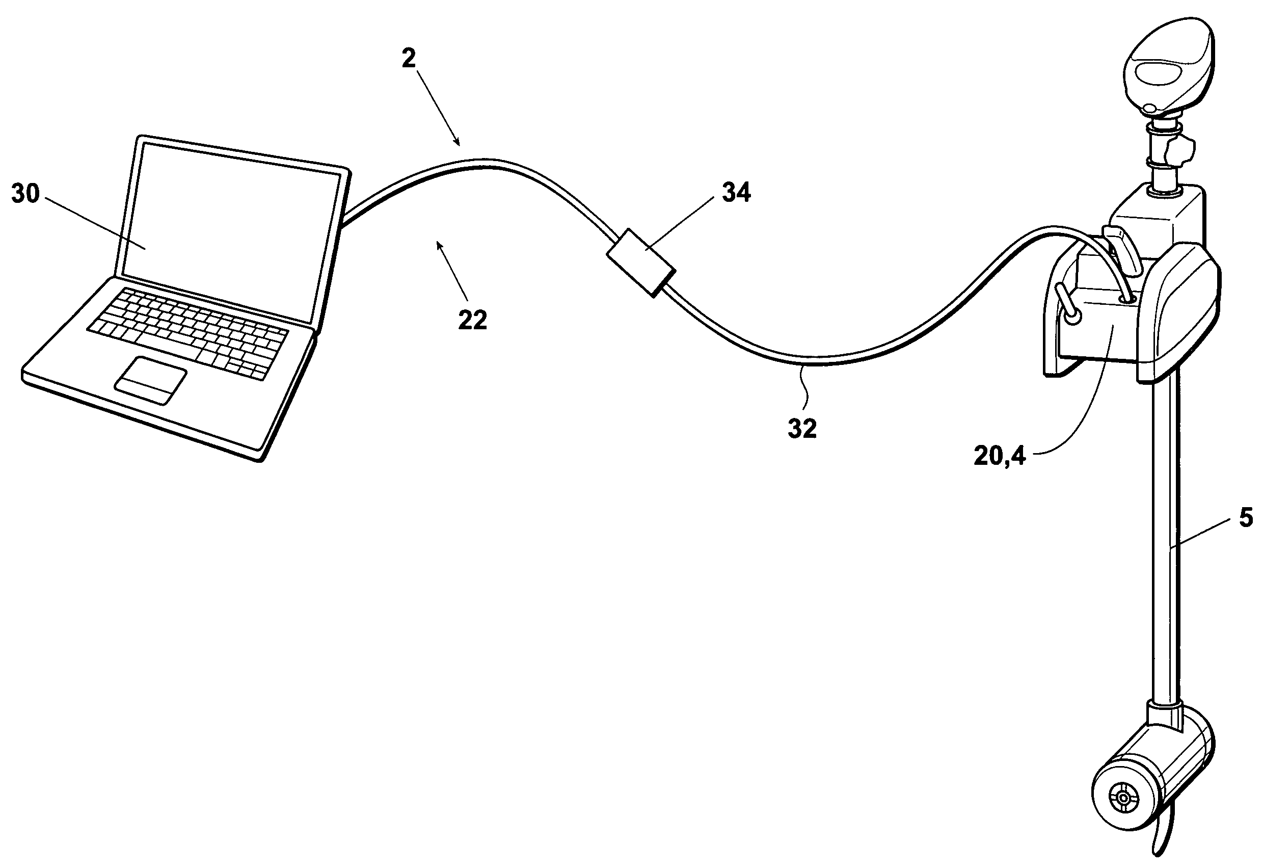
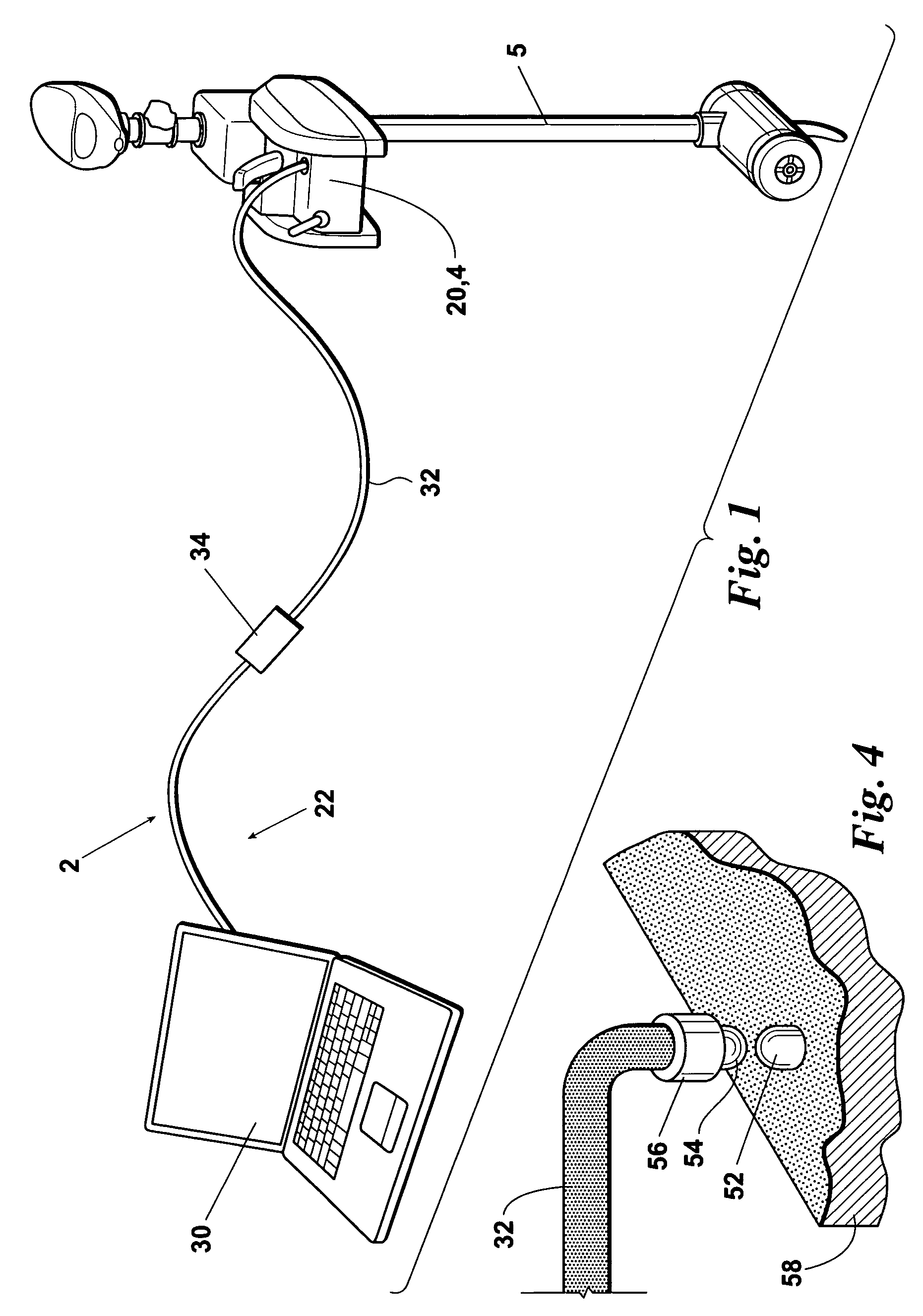
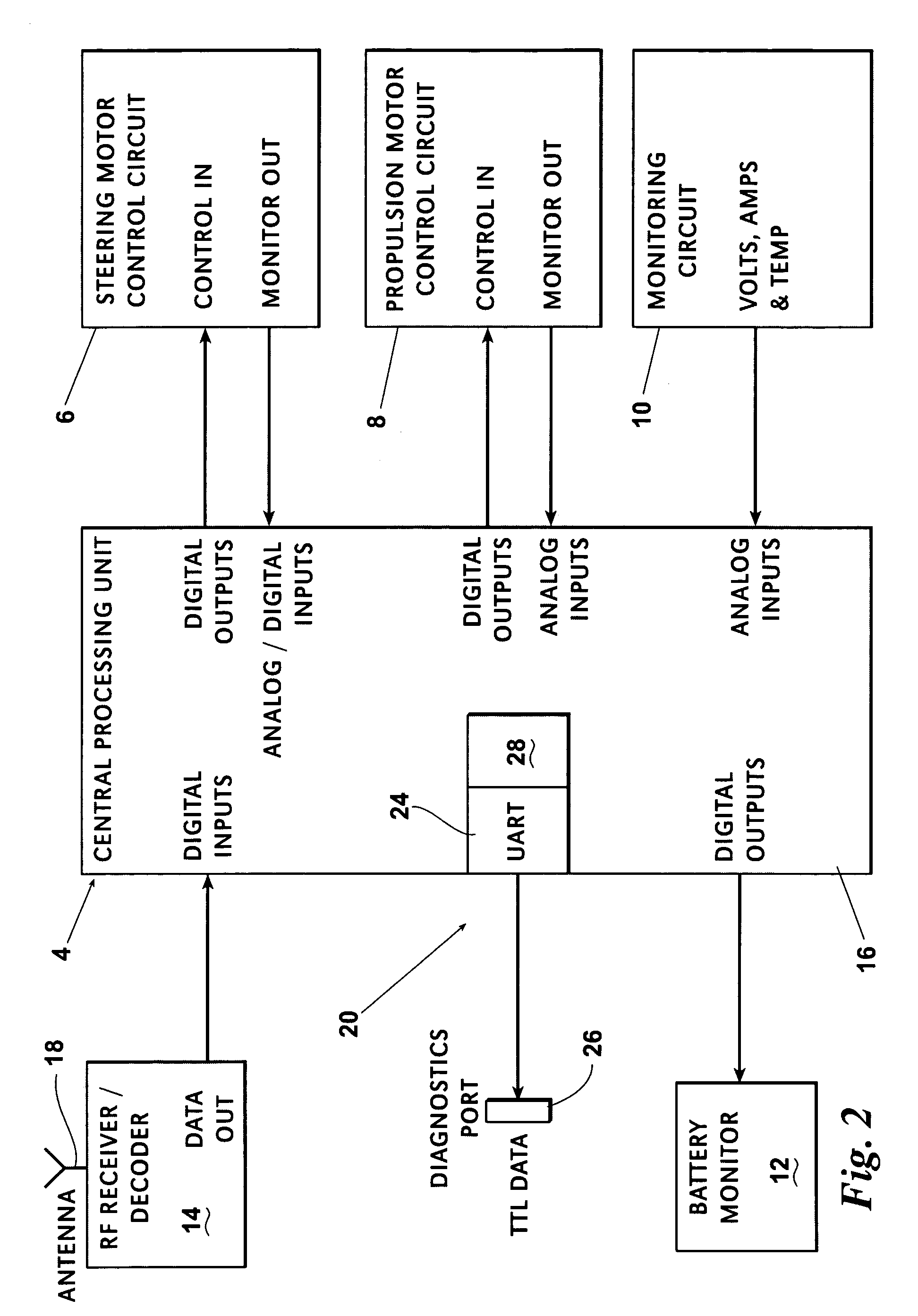
[0023]In the embodiment 2 of the present invention illustrated in FIGS. 1 and 2, the inventive integral electronic diagnostic system 20 preferably comprises: an universal asynchronous receiver / transmitter (UART) 24 which is added to or linked to the trolling motor central processing unit 16; a diagnostics port 26 linked to the UART 24; and an internal nonvolatile electronic memory 28 which is included in or linked to the trolling motor central processing unit 16. The internal nonvolatile memory 28 stores historical diagnostic data received from the trolling motor operational subsystems 6-14 and / or from elsewhere in the trolling motor 5. Examples of historical diagnostic data which could be stored in the internal nonvolatile memory 28 include, but are not limited to, the occurrence and duration of over-current conditions, the occurrence and duration of over-temperature conditions, etc.
[0024]When the trolling motor 5 is activated, the UART preferably transmits both (a) historical diag...
embodiment 50
[0027]Another embodiment 50 of the inventive trolling motor diagnostic system is depicted in FIGS. 3 and 4. The inventive diagnostic system 50 is essentially identical to the inventive diagnostic system 2 except that, rather than using a direct cable connection between the integral electronic diagnostic system 20 and the external diagnostic data processing system 22, the inventive system 50 utilizes a wireless diagnostic data transmission and receiving system. The wireless data and transmission receiving system preferably comprises: (a) an infrared light-emitting diode 52 which replaces the diagnostics connection port 26 of the inventive system 2 and (b) a corresponding infrared phototransistor 54 and amplifier 56 provided on the end of the external diagnostic data system cable 32 for receiving the IR signals transmitted by the infrared light-emitting diode 52. The diagnostic information provided by the embodiment 50 of the inventive system can be transmitted to the external diagnos...
PUM
| Property | Measurement | Unit |
|---|---|---|
| temperature | aaaaa | aaaaa |
| current | aaaaa | aaaaa |
| voltage | aaaaa | aaaaa |
Abstract
Description
Claims
Application Information