Air bag coating composition
a technology of air bags and coating compositions, which is applied in the directions of transportation and packaging, pedestrian/occupant safety arrangements, vehicular safety arrangements, etc., can solve the problems of lack of compactness of prior art failure of conventional rubber coating compositions used in plain weave type air bags to hold the same inflation time for hollow weave type air bags
- Summary
- Abstract
- Description
- Claims
- Application Information
AI Technical Summary
Benefits of technology
Problems solved by technology
Method used
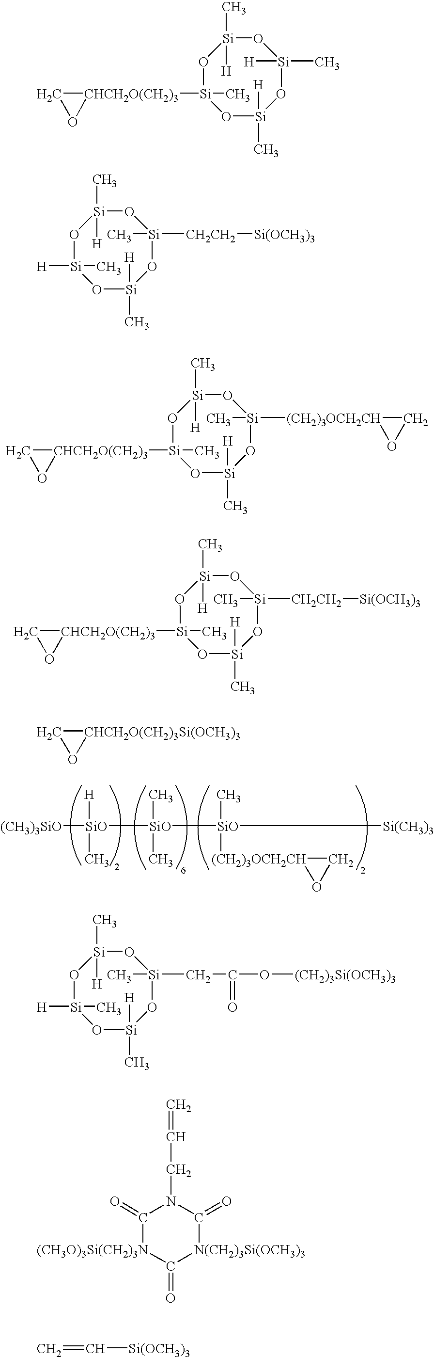
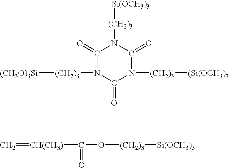
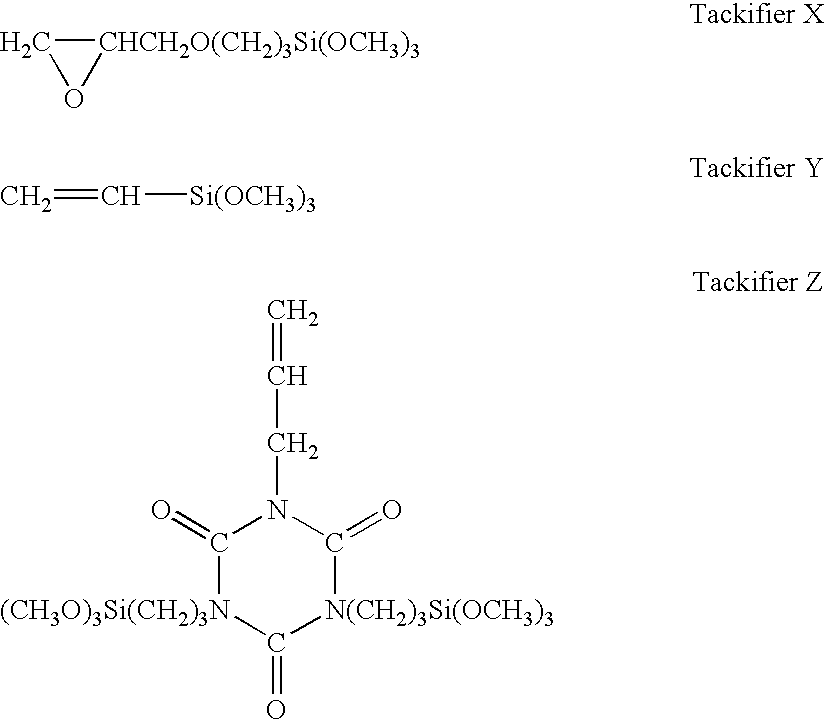
Image

Examples
example 1
[0046]A composition A was prepared by mixing the following: 80 parts of a dimethylvinylsiloxy end-capped dimethylpolysiloxane and having a viscosity of 10 Pa·s, 4 parts of a trimethylsiloxy end-capped dimethylsiloxane-methylvinylsiloxane copolymer containing 5 mol % of vinylmethylsiloxane units and 95 mol % of dimethylsiloxane units in the diorganosiloxane units of the backbone and having a viscosity of 0.7 Pa·s, 17 parts of hydrophobic silica treated with trimethylsilyl groups and having a specific surface area of 120 m2 / g, 1.0 part of a trimethylsiloxy end-capped methylhydrogenpolysiloxane (silicon atom-bonded hydrogen atom content=1.45 wt %) having a viscosity of 5 mPa·s, 2.2 parts of a dimethylsiloxane-methylhydrogensiloxane copolymer having silicon atom-bonded hydrogen atoms at both ends and side chains of the molecular chain (silicon atom-bonded hydrogen atom content=0.54 wt %) and having a viscosity of 12 mPa·s (giving H / Vi=3.9 mol / mol), 0.05 part of 1-ethynyl cyclohexanol, a...
example 2
[0050]A composition B was prepared by mixing the following: 17 parts of a dimethylvinylsiloxy end-capped dimethylpolysiloxane and having a viscosity of 100 Pa·s, 33 parts of a dimethylvinylsiloxy end-capped dimethylpolysiloxane and having a viscosity of 10 Pa·s, 30 parts of a dimethylvinylsiloxy end-capped dimethylpolysiloxane and having a viscosity of 1 Pa·s, 3 parts of a trimethylsiloxy end-capped dimethylsiloxane-methylvinylsiloxane copolymer containing 10 mol % of vinylmethylsiloxane units and 90 mol % of dimethylsiloxane units in the diorganosiloxane units of the backbone and having a viscosity of 0.7 Pa·s, 5 parts of an organopolysiloxane resin consisting of 39.5 mol % of (CH3)3SiO1 / 2 units, 6.5 mol % of (CH3)2(CH2═CH)SiO1 / 2 units, and 54 mol % of SiO2 units, 22 parts of hydrophobic silica treated with trimethylsilyl groups and having a specific surface area of 170 m2 / g, 1.8 part of a trimethylsiloxy end-capped methylhydrogenpolysiloxane (silicon atom-bonded hydrogen atom cont...
PUM
| Property | Measurement | Unit |
|---|---|---|
| viscosity | aaaaa | aaaaa |
| viscosity | aaaaa | aaaaa |
| degree of polymerization | aaaaa | aaaaa |
Abstract
Description
Claims
Application Information
 - R&D
- Intellectual Property
- Life Sciences
- Materials
- Tech Scout
- Unparalleled Data Quality
- Higher Quality Content
- 60% Fewer Hallucinations
Browse by: Latest US Patents, China's latest patents, Technical Efficacy Thesaurus, Application Domain, Technology Topic, Popular Technical Reports.
© 2025 PatSnap. All rights reserved.Legal|Privacy policy|Modern Slavery Act Transparency Statement|Sitemap|About US| Contact US: help@patsnap.com