Current transformer, circuit interrupter including the same, and method of manufacturing the same
a current transformer and circuit interrupter technology, applied in the field of circuit interrupters, can solve the problems of inability of the ct core to handle extreme changes in magnetic flux and the inability of the known ct to accurately sense current, and achieve the effect of increasing the permeability of the generally circular cylindrical current transformer cor
- Summary
- Abstract
- Description
- Claims
- Application Information
AI Technical Summary
Benefits of technology
Problems solved by technology
Method used
Image

Examples
example 1
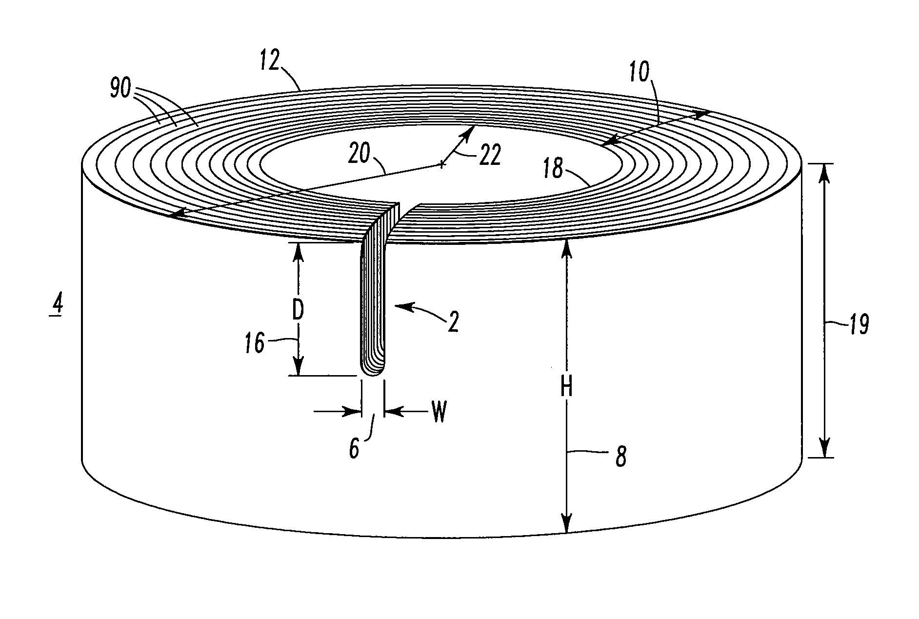
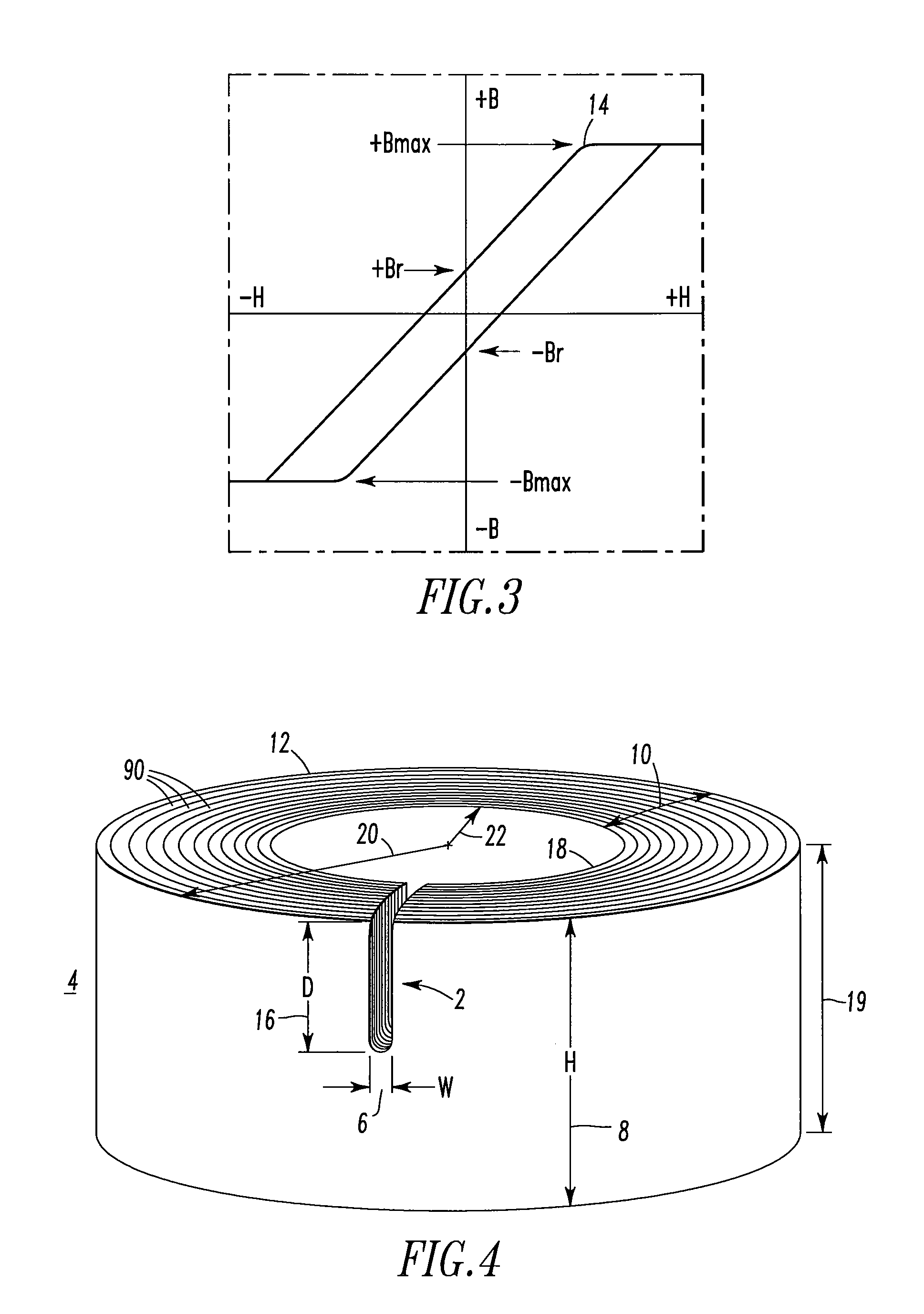
[0037]The magnetic properties of electrical steels are especially sensitive to stress. Stresses that produce plastic deformation cause the greatest changes in the magnetic properties of the material being processed. These changes occur because the metal crystals in the stressed metal have been distorted. This distortion of the crystal structure affects the relationship between the magnetizing force and induction. In order to remove the stresses caused by plastic deformation, annealing is required to return the material to a stress-free condition. Accordingly, CT core 4 should be annealed in its final form. This means that all processes that caused the stresses, including, for example, core winding and gapping have been completed. The finished CT core 4 should be stress annealed at temperatures between about 1450° F. to about 1550° F. for at least about one hour. This stress annealing ensures recrystallization of the core material and restoration of the desired magnetic properties.
example 2
[0038]FIG. 5 shows a current transformer 30 including the CT core 4 of FIG. 4 and a secondary winding 32 (e.g., without limitation, structured for about a 225 A primary current; any suitable primary current). The current transformer 30 further includes a label 34 (e.g., without limitation, showing part number and date code information), a connector housing 36, two connector pins 38, and two insulated conductors 40,42, which exit the secondary winding 32 of the current transformer 30. The secondary winding 32 is disposed about the CT core 4. A suitable insulating tape 44 (e.g., without limitation, Kapton®) covers the secondary winding 32.
[0039]In this example, the wire size of the secondary winding 32 of the current transformer 30 is 35 AWG and has 3,750 turns with a resistance of about 177.7 ohms. The outside diameter 46 of the current transformer 30 is about 1.1 inches, the diameter 48 of the central opening 50 of the current transformer 30 is about 0.28 inch, the height 52 of the ...
example 3
[0045]FIG. 6 shows a circuit interrupter, such as molded case circuit breaker 60, including a housing (not shown) in which a number of separable contacts 62 (e.g., without limitation, a pair per each phase) are contained. The separable contacts 62 are associated with conductors 64 of a power distribution system including three example phases. The separable contacts 62 may be operated automatically in response to an overcurrent condition. The separable contacts 62 may also be operated manually by way of an operating handle (not shown) disposed on the outside of the circuit breaker 60. As is conventional, the circuit breaker 60 includes an operating mechanism 66, which is structured to open and close the separable contacts 62, and a trip unit, such as trip assembly 68, which senses overcurrent conditions. Upon sensing an overcurrent condition, the trip assembly 68 actuates the operating mechanism 66 to a trip position, which moves the separable contacts 62 to their open position, as s...
PUM
| Property | Measurement | Unit |
|---|---|---|
| temperature | aaaaa | aaaaa |
| dielectric breakdown tests | aaaaa | aaaaa |
| temperature | aaaaa | aaaaa |
Abstract
Description
Claims
Application Information
PatSnap Eureka turns technology decisions into work you can execute. Powered by our Innovation Knowledge Graph, it runs expert workflows across engineering, life sciences, materials and intellectual property. Get your review-ready output in minutes.


