Fuel injection method

a fuel injection and electric control technology, applied in the direction of electric control, machines/engines, applications, etc., can solve the problems of increasing the number of components and difficulty in accurately correcting the fuel injection amount, and achieve the effect of accurately correcting the drive pulse width

Inactive Publication Date: 2007-12-18
MIKUNI CORP
View PDF14 Cites 18 Cited by
  • Summary
  • Abstract
  • Description
  • Claims
  • Application Information

AI Technical Summary

Benefits of technology

[0012]According to the invention described in claim 1, the offset component can be detected by calculating difference current between coil currents respectively detected before and after every driving the solenoid, to correct the drive pulse width accurately by eliminating the offset component.
[0014]According to the invention described in claim 2, an appropriate current span can be set to correct the drive pulse width accurately.
[0016]According to the invention described in claim 3, the offset component can be eliminated for every driving of the solenoid that generates the offset component, to correct the drive pulse stably for long periods by eliminating the influence of temperature drift.
[0018]According to the invention described in claim 4, the current span can be calculated for each product to correct the drive pulse width accurately using the current span of each product.

Problems solved by technology

Therefore, it is difficult to correct the fuel injection amount accurately.
In this case, however, it causes an increase in the number of components due to the complex controller and an increase in software processing.

Method used


Image

  • Fuel injection method
  • Fuel injection method
  • Fuel injection method

Examples


Embodiment Construction

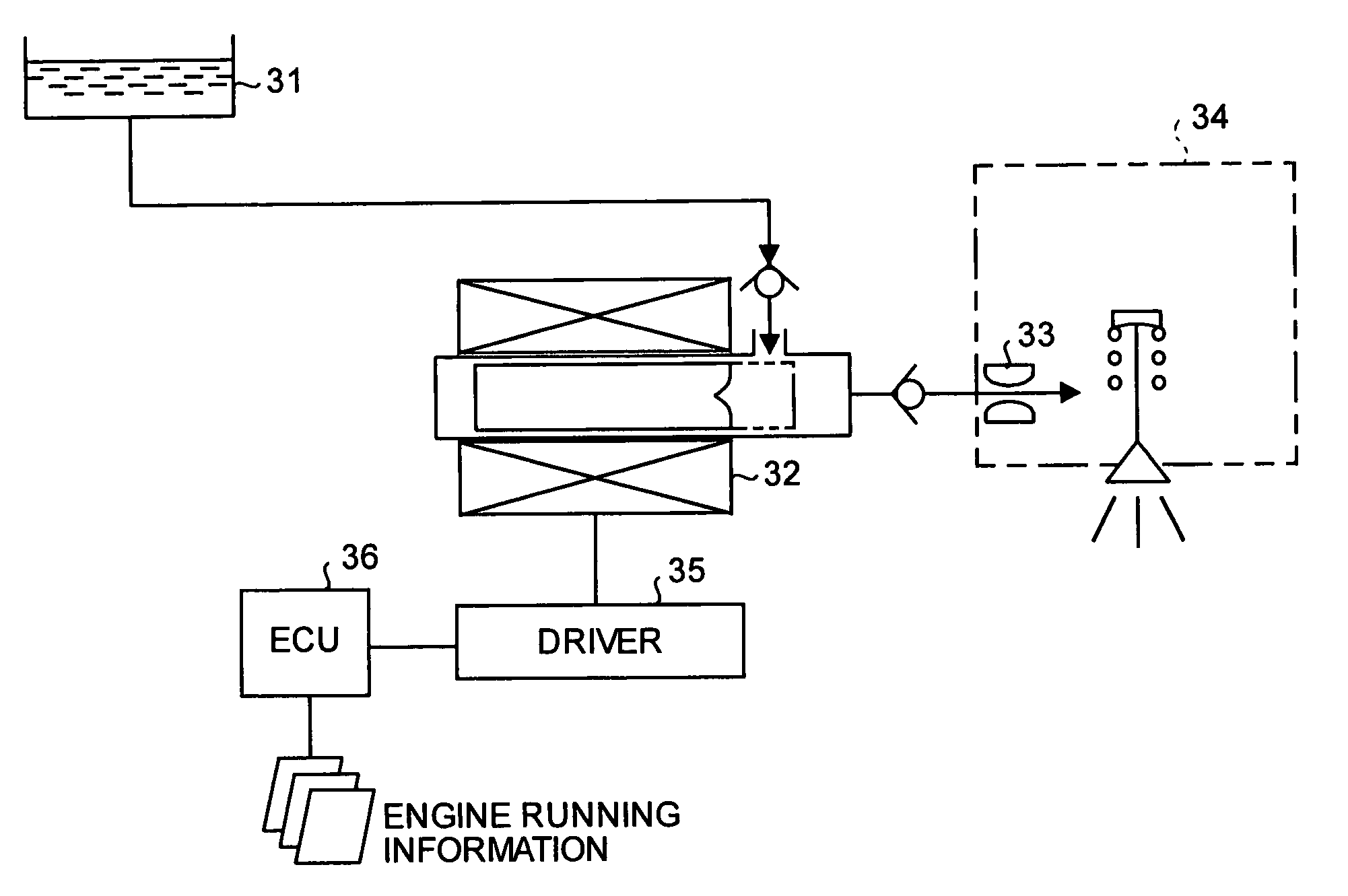
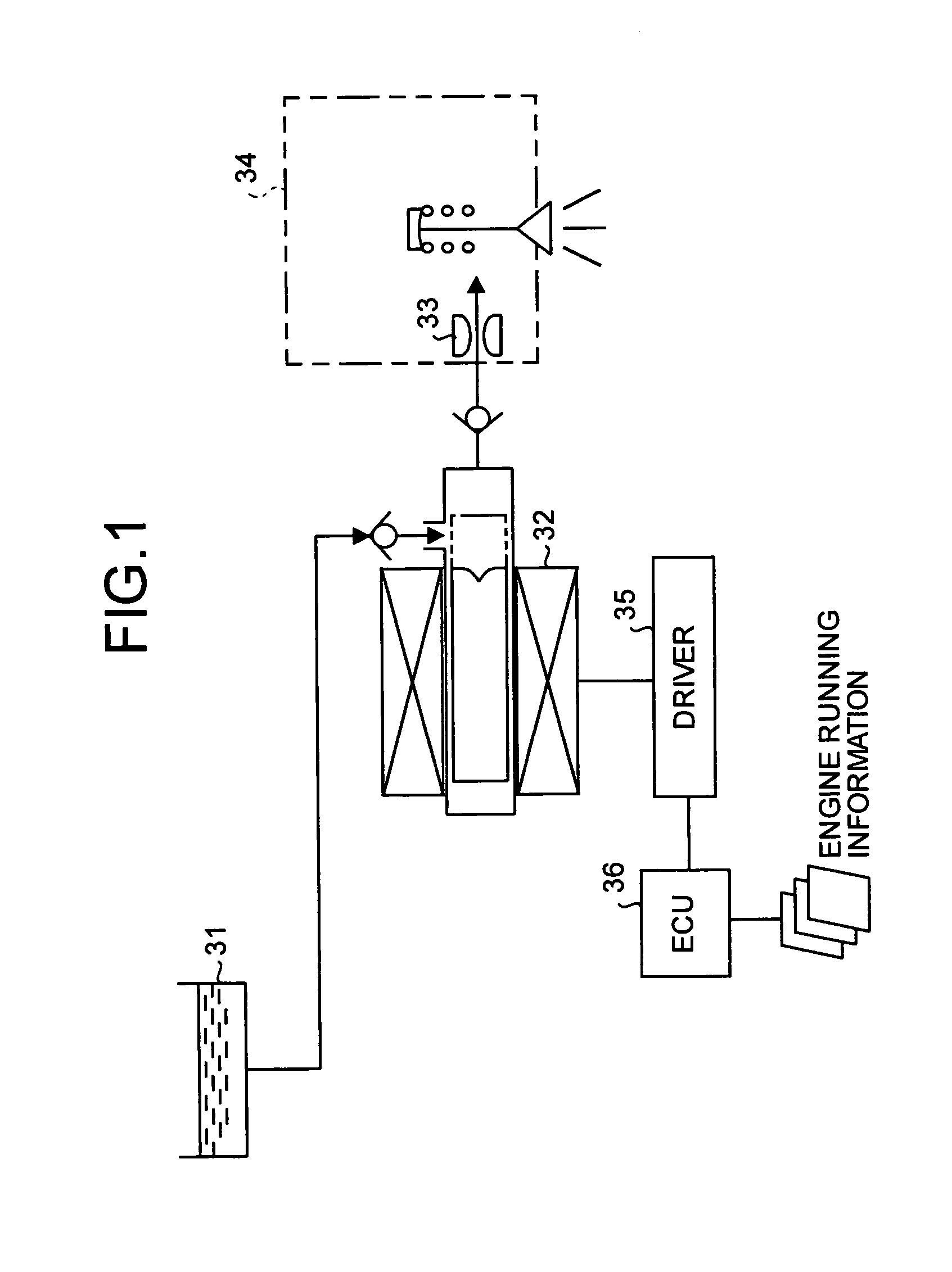
[0032]Exemplary embodiments of the present invention will be described below in detail, with reference to the drawings. First explained is a configuration of an electromagnetic fuel injection pump system applying a fuel injection method according to the present invention. FIG. 1 is a diagram of the overall configuration of the electromagnetic fuel injection pump system applying the fuel injection method according to the present invention.

[0033]As shown in FIG. 1, the electromagnetic fuel injection pump system includes the following basic constituents 31 to 36, for example. A plunger pump 32 serves as an electromagnetic driving pump that can press-send fuel from inside a fuel tank 31. An inlet orifice nozzle 33 has an orifice that allows the fuel pressurized under a certain pressure and sent from the plunger pump 32 to pass therethrough. An injection nozzle 34 injects the fuel into an intake manifold (in an engine) when the fuel passing through the inlet orifice nozzle 33 is pressuri...


PUM


Abstract

A fuel injection method is provided for correcting the fuel injection amount accurately by eliminating offset components when detecting a current flowing through a solenoid for fuel injection. A current component, which is detected during normal running and a drive current flowing through the solenoid for fuel injection is OFF (Step 11), is input to an A / D converter that stores the value thereof (Step 12). Thereafter, the drive current is turned ON (Step S13), elapse of a fixed time period is waited (Step S14), and an input voltage of the A / D converter is detected (Step S15). A difference current (offset component) is calculated by subtracting the offset voltage from the input voltage (Step S16), and a current span is adjusted based on a span correction factor (Step S17). Thereafter, a pulse width current correction factor is calculated (Step S2a) and, based on the pulse width current correction factor, a drive pulse width is calculated (Step S2b) and provided to the solenoid.

Description

TECHNICAL FIELD[0001]The present invention relates to an electronically controlled fuel injection method for supplying fuel to engines. More particularly, the present invention relates to a fuel injection method for injecting fuel accurately without being affected by variations in supply voltage or in coil resistance of a solenoid included in a fuel injector.BACKGROUND ART[0002]FIG. 8 is a diagram of a correction control system in a conventional fuel injector. In the control system, a supply voltage VB of a supply terminal 11 is input to a microcomputer 13 in an electronic control unit (hereinafter, “ECU”) via a supply voltage input circuit 12.[0003]When the supply voltage VB is low, the microcomputer 13 provides a field effect transistor (hereinafter, “FET”) driver 15 with a pulse having such a waveform that elongates the on-time period of an FET 14. As a result, a coil current flows through a solenoid 16 for a longer time to elongate a fuel injection time. When the supply voltage ...

Claims


Application Information

Patent Timeline
Patent Type & Authority Patents(United States)
IPC IPC(8): F02D1/06A01G27/00B05B1/30F02M47/02F02M59/00F02M51/00F02D41/20F02D41/24F02D41/34
CPCF02D41/20F02D2041/2058
Inventor YAMAZAKI, SHIGERUHIROSAWA, HIROKAZU
Owner MIKUNI CORP
Why Eureka
Try Eureka