
Light source apparatus and projection display apparatus

a technology of projection display and light source, which is applied in the direction of lighting and heating apparatus, instruments, and semiconductor/solid-state device details, etc., can solve the problems of insufficient cooling effect, noise from fans, and deterioration of light emission efficiency, so as to reduce the number of operations needed to assemble these heat dissipation members and circulation members, easy to avoid interference, and easy to reduce the number of operations. , the effect of reducing the number of operations

Active Publication Date: 2007-12-18
SEIKO EPSON CORP
View PDF21 Cites 52 Cited by
  • Summary
  • Abstract
  • Description
  • Claims
  • Application Information

AI Technical Summary

Benefits of technology

The solution effectively increases the power input to the LED light source, enhancing luminance while maintaining a compact size, and improves cooling efficiency by converting laminar flow to turbulent flow and increasing the heat transfer surface area, thus addressing the brightness and heat management issues.

Problems solved by technology

However, because the brightness of an LED light source is insufficient as the light source of a projector, for an LED light source to be used as the light source of a projector, it has been necessary to ensure at least the level of brightness of a discharge type of light source lamp (i.e., it has been necessary to raise the luminance and lower the etendue).
However, if the temperature of an LED light source rises, the light emission efficiency thereof deteriorates, so that some type of countermeasure against heat has been required.
In the forced air-cooling system using a fan that is generally employed, the cooling effect is insufficient and the noise from the fan has created problems.
However, because the structure of the LED light source is complex such as an insulating casing being necessary and the like, the manufacture thereof is not practical.
Therefore, the problem arises that it is difficult to ensure at the least the brightness level of a discharge type light source lamp.
However; a device for actively cooling the insulating inert liquid is not provided, so that the cooling effect is low and it is difficult to cool an LED chip for an extended period of time.
Consequently, the problem arises that it is difficult to ensure at the least the brightness level of a discharge type light source lamp.

Method used


Image

  • Light source apparatus and projection display apparatus
  • Light source apparatus and projection display apparatus
  • Light source apparatus and projection display apparatus

Examples


first embodiment

[0170]A description will now be given of a projection display apparatus that is the first embodiment of the second aspect of the present invention with reference made to FIGS. 29 through 38.

[0171]FIG. 29 is a schematic diagram of a projection display apparatus 500 that is provided with the light source apparatus according to the present embodiment. In FIG. 29, the symbols 512, 513, and 514 show a light source apparatus of the present embodiment; the symbols 522, 523, and 524 show liquid crystal light bulbs (i.e., optical modulating means); the symbol 525 shows a cross-dichroic prism (i.e., a photosynthesizing means); and the symbol 526 shows a projection lens (i.e., a projection means).

[0172]The projection display apparatus 500 shown in FIG. 29 is provided with three light source apparatuses 512, 513, and 514 that are structured as described in the present embodiment. LED that respectively emit red (R), green (G), and blue (B) light are employed in the respective light source appara...

second embodiment

[0216]Next, the second embodiment of the second aspect of the present invention will be described with reference made to FIG. 39.

[0217]The basic structure of the projection display apparatus of the present embodiment is the same as that in the first embodiment, however, the light source apparatuses are different from those in the first embodiment. Accordingly, in the present embodiment, a description is only given of the area around the light source apparatuses using FIG. 39, and a description of the liquid crystal light bulbs is omitted.

[0218]FIG. 39 is a schematic view showing a light source apparatus of the projection display apparatus of the second aspect of the present invention.

[0219]In the light source apparatuses 612, 613, and 614, only the LED chips (solid state light sources) 121r, 121g, and 121b that emit the respective red (R), green (G), blue (B) colored light are different from each other. Therefore, here, a description is only given of the light source apparatus 612 t...

third embodiment

[0236]Next, the third embodiment of the second aspect of the present invention will be described with reference made to FIG. 40.

[0237]The basic structure of the projection display apparatus of the present embodiment is the same as that in the first embodiment, however, the light source apparatuses are different from those in the first embodiment. Accordingly, in the present embodiment, a description is only given of the area around the light source apparatuses using FIG. 40, and a description of the liquid crystal light bulbs is omitted.

[0238]FIG. 40 is a schematic view showing a light source apparatus of the projection display apparatus of the second aspect of the present invention.

[0239]In the light source apparatuses 712, 713, and 714, only the LED chips (solid state light sources) 121r, 121g, and 121b that emit the respective red (R), green (G), blue (B) colored light are different from each other. Therefore, here, a description is only given of the light source apparatus 712 th...


PUM


Abstract

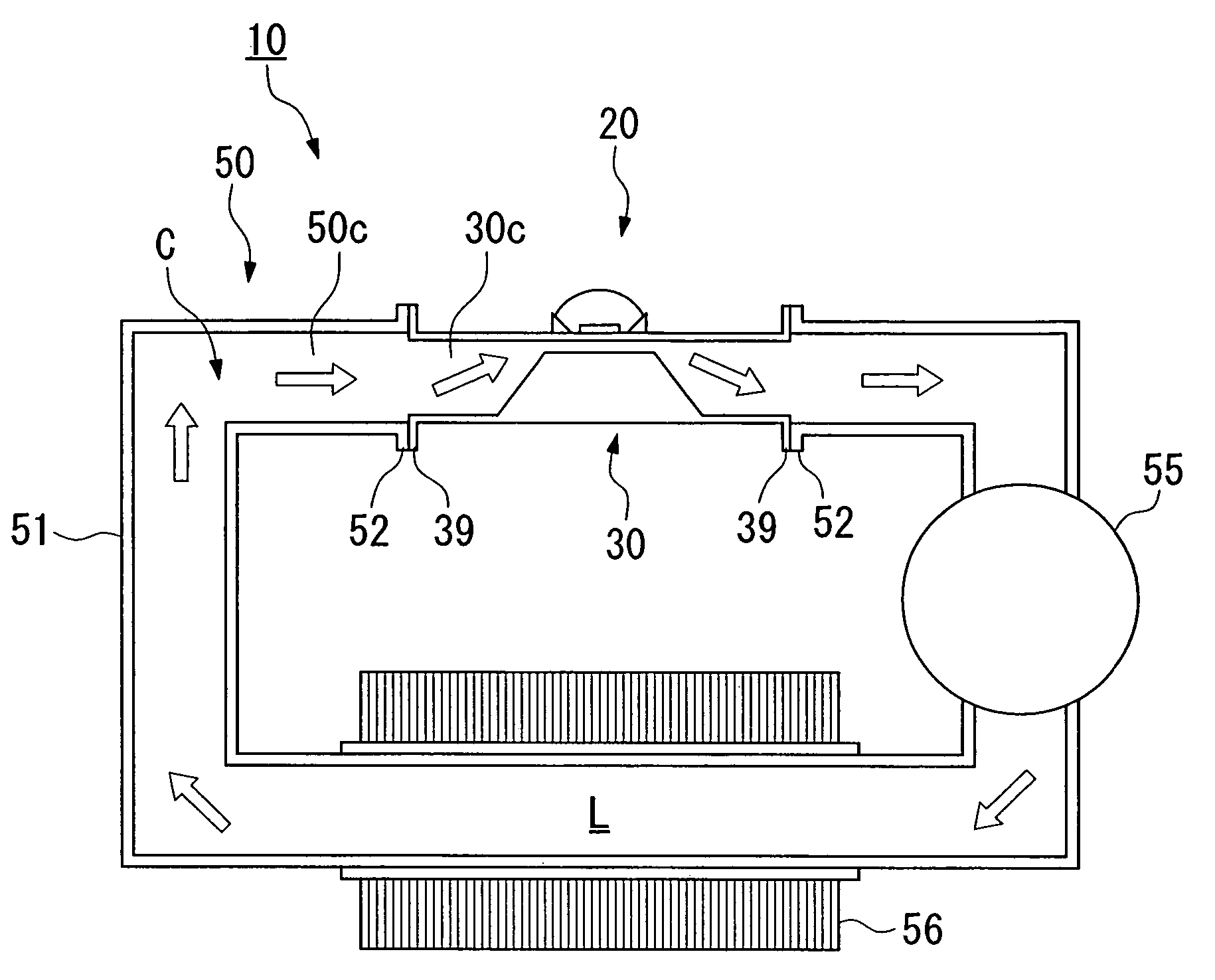
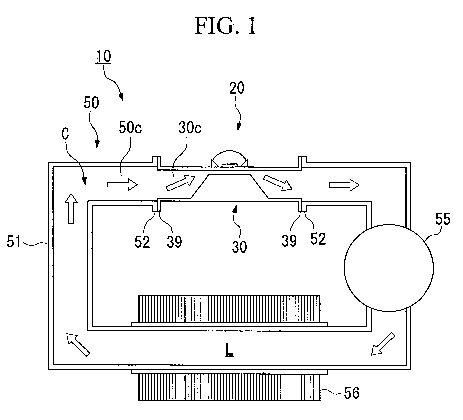
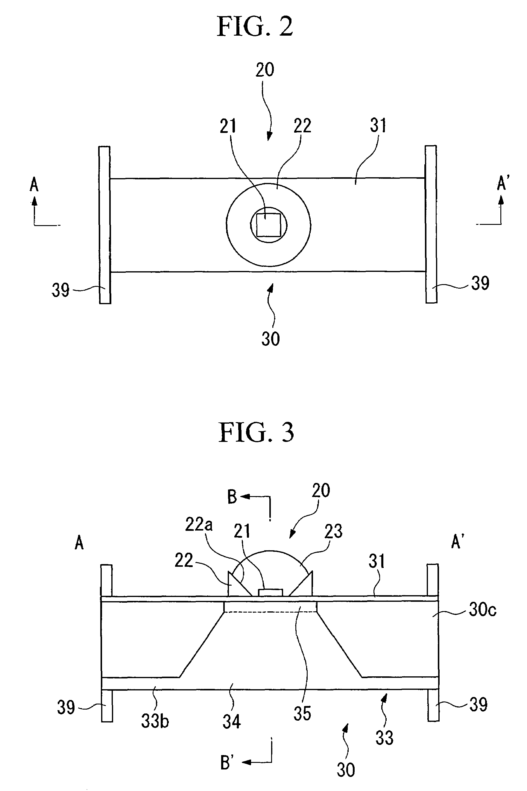
A light source apparatus including: a solid state light source that includes a pair of electrodes and emits light in response to power being supplied with from the electrodes; a liquid medium that removes heat that is generated in the solid state light source; and a mounting unit which is provided a flow path in an interior thereof in which the liquid medium flows, including: a base that defines the flow path; and a placement member which defines a remainder of the flow path and on which the solid state light source is mounted.

Description

BACKGROUND OF THE INVENTION[0001]1. Field of the Invention[0002]The present invention relates to a light source apparatus and a projection type display apparatus.[0003]Priority is claimed on Japanese Patent Application No. 2004-5411, filed Jan. 13, 2004, Japanese Patent Application No. 2004-7903, filed Jan. 15, 2004, and Japanese Patent Application No. 2004-330534, filed Nov. 15, 2004 the contents of which are incorporated herein by reference.[0004]2. Description of Related Art[0005]Projectors (i.e., projection type display apparatuses) have in recent years achieved reductions in size, improvements in luminance, longer life spans, and reductions in cost. For example, as far as size reductions are concerned, the size of liquid crystal panels (i.e., optical modulators) has been reduced from 1.3 inches diagonally to 0.5 inches so that a size reduction of more than one sixth (as a surface ratio) is achieved.[0006]It has also been proposed that a reduction in size can be achieved by usin...

Claims


Application Information

Patent Timeline
Patent Type & Authority Patents(United States)
IPC IPC(8): F21V29/00H05K7/20F21V29/02G03B21/20H01L33/64
CPCF21V29/30G03B21/2033H01L33/648G03B21/16F21Y2101/02H01L33/642F21Y2115/10F21V29/56F21V29/70
Inventor NAGATA, MITSUOSETO, TAKESHITAKAGI, KUNIHIKOIKEBE, TOMO
Owner SEIKO EPSON CORP
Learn More