Method for determining the rotor position of a synchronous motor

a synchronous motor and rotor position technology, applied in the direction of synchronous motor starters, single motor speed/torque control, electronic commutators, etc., can solve the problems of increasing the current needed for generating a rotor movement, affecting the synchronous motor's synchronous motor's synchronous motor's synchronous motor, and affecting the synchronous motor's synchronous motor's synchronous motor. the effect of increasing the current required

Active Publication Date: 2007-12-18
DR JOHANNES HEIDENHAIN GMBH
View PDF7 Cites 9 Cited by
  • Summary
  • Abstract
  • Description
  • Claims
  • Application Information

AI Technical Summary

Benefits of technology

[0005]An example embodiment of the present invention may provide a simple method by which it is possible to determine the rotor position of a synchronous motor.
[0006]In certain cases, it may be provided to initially lock the rotor of the synchronous motor using a brake. Such a brake may be available in many applications, for example, in machine tools where, for safety reasons, electrical and mechanical motor brakes are customary for all axes. The holding force of such a brake is great compared to grooving forces of the synchronous motor or forces applied to the rotor by machine vibrations. These effects are therefore insignificant for the subsequent determination of the rotor position. It is thus possible to work with very small deflections of the rotor, which are still allowed even in critical applications. If the synchronous motor is held by a great static friction, even without a brake, then the engagement of a brake may be needless, since the static friction ultimately acts like an engaged brake.

Problems solved by technology

A disadvantage in this method, however, is that relatively large movements of the rotor must be brought about before the resulting direction of rotation can be unequivocally detected with the aid of a position-measuring instrument.
If these movements are selected to be too small, then grooving forces and machine vibrations can lead to a false result.
However, larger movements are problematic and are not allowed in all cases, for instance, when a synchronous motor is driving a tool that is already engaged with a workpiece.
Another disadvantage of this method is that the current necessary for generating a movement of the rotor becomes increasingly greater, the narrower the angular range becomes.
The accuracy of the method is thus limited by the maximum possible current.
If the synchronous motor is held by a great static friction, even without a brake, then the engagement of a brake may be needless, since the static friction ultimately acts like an engaged brake.
The measurement of the amount of the current vector necessary for attaining a defined deflection may thus be broken off when the current reaches a limiting value, without the accuracy of the rotor-position determination thereby suffering.

Method used


Image

  • Method for determining the rotor position of a synchronous motor
  • Method for determining the rotor position of a synchronous motor
  • Method for determining the rotor position of a synchronous motor

Examples


Embodiment Construction

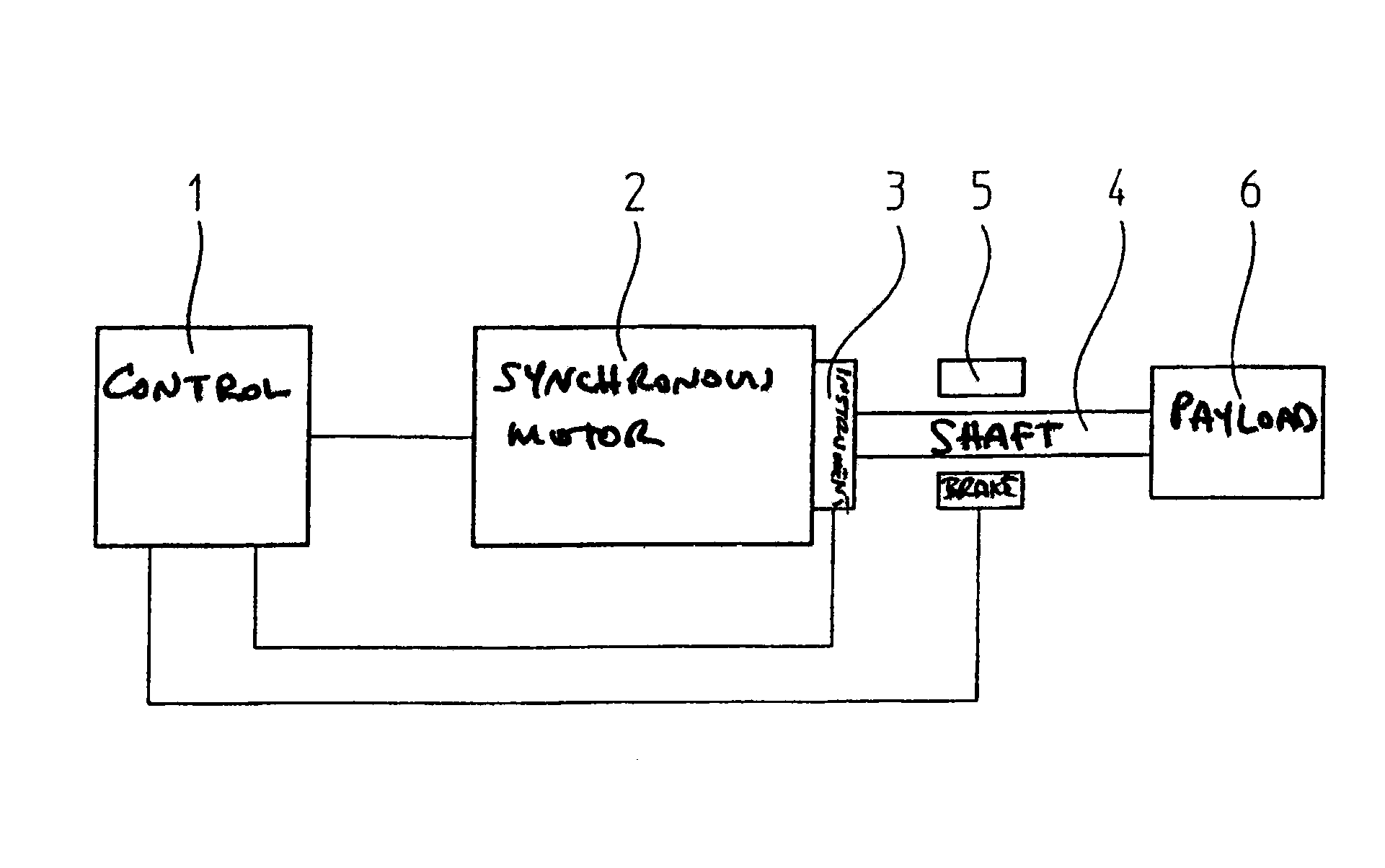
[0017]FIG. 1 illustrates a drive unit having a synchronous motor 2 that is triggered via a control 1. The rotor position of synchronous motor 2 is monitored via a position-measuring instrument 3 that, for example, may be an incremental rotary transducer that only allows the calculation of absolute position values after a reference point has been overtravelled. Position-measuring instrument 3 is connected to shaft 4 of synchronous motor 2. Since shaft 4 is rigidly connected to the rotor of synchronous motor 2, it is possible to infer the position of the rotor from the position of shaft 4. If necessary, a brake 5 may act upon shaft 4. Such mechanical or electrical brakes 5 may be used to quickly brake movements in case of emergency or to keep suspended axles in the de-energized state. Brake 5 may be activated via control 1. A payload 6 is driven via shaft 4. For example, this may be the tool spindle of a machine tool, or also a linear axle of the machine tool that is driven via a spin...


PUM


Abstract

The rotor position of a synchronous motor is determined, in that for a plurality of current vectors distributed over one electrical rotation of the synchronous motor, the amount of the current vector which is necessary to attain a defined deflection of the rotor is determined. The position of the rotor may be calculated from the position of the minima of the amounts thus determined, taking into account the direction of rotation of the rotor. The engagement of a brake may ensure that grooving forces and machine vibrations play no role for the method to determine the rotor position.

Description

FIELD OF THE INVENTION[0001]The present invention relates to a method for determining the rotor position of a synchronous motor. Such a method may be necessary, for example, to start a synchronous motor that is monitored by a position-measuring instrument which only delivers unequivocal commutation signals after a reference position has been overtravelled.BACKGROUND INFORMATION[0002]Numerous methods are conventional by which it is possible to determine the position of the rotor of a synchronous motor in order to permit the electrical commutation of the motor, even without position information from a position-measuring instrument. Many of these methods are based on complicated measurements of the inductances of the primary-circuit coils or the measurement and evaluation of the electromotive counterforce. Such methods make it possible to operate a synchronous motor completely without a position-measuring instrument.[0003]If for the start-up or when putting the synchronous motor into o...

Claims


Application Information

Patent Timeline
Patent Type & Authority Patents(United States)
IPC IPC(8): H02P21/00H02P6/08H02P6/18H02P6/16
CPCH02P6/16
Inventor KRANITZKY, WALTERQUENTEL, GERHARD
Owner DR JOHANNES HEIDENHAIN GMBH
Why Eureka
Try Eureka