Data recovery circuit, phase detection circuit and method for detecting and correcting phase conditions

a phase detection and data recovery technology, applied in the field of data recovery circuits, can solve the problems of significantly reducing the effective period for valid sampling of data bits, and the difficulty of generating a sampling clock with such a high frequency

Active Publication Date: 2007-12-18
XUESHAN TECH INC
View PDF6 Cites 35 Cited by
  • Summary
  • Abstract
  • Description
  • Claims
  • Application Information

AI Technical Summary

Benefits of technology

[0011]The object of the present invention is to provide a data recovery circuit having a sampling circuit that can be operated at a lower frequency. Therefore, the data recovery circuit is suitable for applications of high frequency serial data transmission.
[0012]Another object of the present invention is to provide a data recovery circuit having a phase detection and correction circuit for dynamically detecting and controlling the phase of a sampling clock signal to ensure that the sampling edges of the clock signal are always locked to the central portions of the data bits to thereby obtain correct recovered data.
[0013]In order to achieve the above objects, the data recovery circuit of the present invention comprises: a clock generator for generating a first group of sampling clock pulses and a second group of sampling clock pulses and being controlled in response to a phase control signal to adjust the phases of the first group of sampling clock pulses and the second group of sampling clock pulses; a data and phase sampling circuit for sampling approximately a central portion of each data bit in an incoming data stream in accordance with the first group of sampling clock pulses to produce a first sampled data stream while sampling approximately a transition portion between every two data bits in the incoming data stream in accordance with the second group of sampling clock pulses to produce a second sampled data stream; and a phase detection and correction circuit for determining the resemblance of each bit in the second sampled data stream to the corresponding two adjacent bits in the first sampled data stream, defining an early condition for the phases of the sampling clocks if each bit in the second sampled data stream resembles the former of the corresponding two adjacent bits in the first sampled data stream while defining a late condition for the sampling clocks if each bit in the second sampled data stream resembles the latter of the corresponding two adjacent bits in the first sampled data stream, and producing the phase control signal on the basis of the early condition or the late condition to adjust the phases of the sampling clocks by shifting the phases backwards or forwards.

Problems solved by technology

However, according to the DVI standard, the differential image signal is transmitted at an extremely high rate, for example, at several giga-hertz (GHz), and it is very difficult to generate a sampling clock with such a high frequency.
Furthermore, in a data transmission high up to several giga-hertz, the transmitted signals are vulnerable to jitters and high-frequency reflective interferences, which significantly reduces the effective period for valid sampling of a data bit.

Method used


Image

  • Data recovery circuit, phase detection circuit and method for detecting and correcting phase conditions
  • Data recovery circuit, phase detection circuit and method for detecting and correcting phase conditions
  • Data recovery circuit, phase detection circuit and method for detecting and correcting phase conditions

Examples


Embodiment Construction

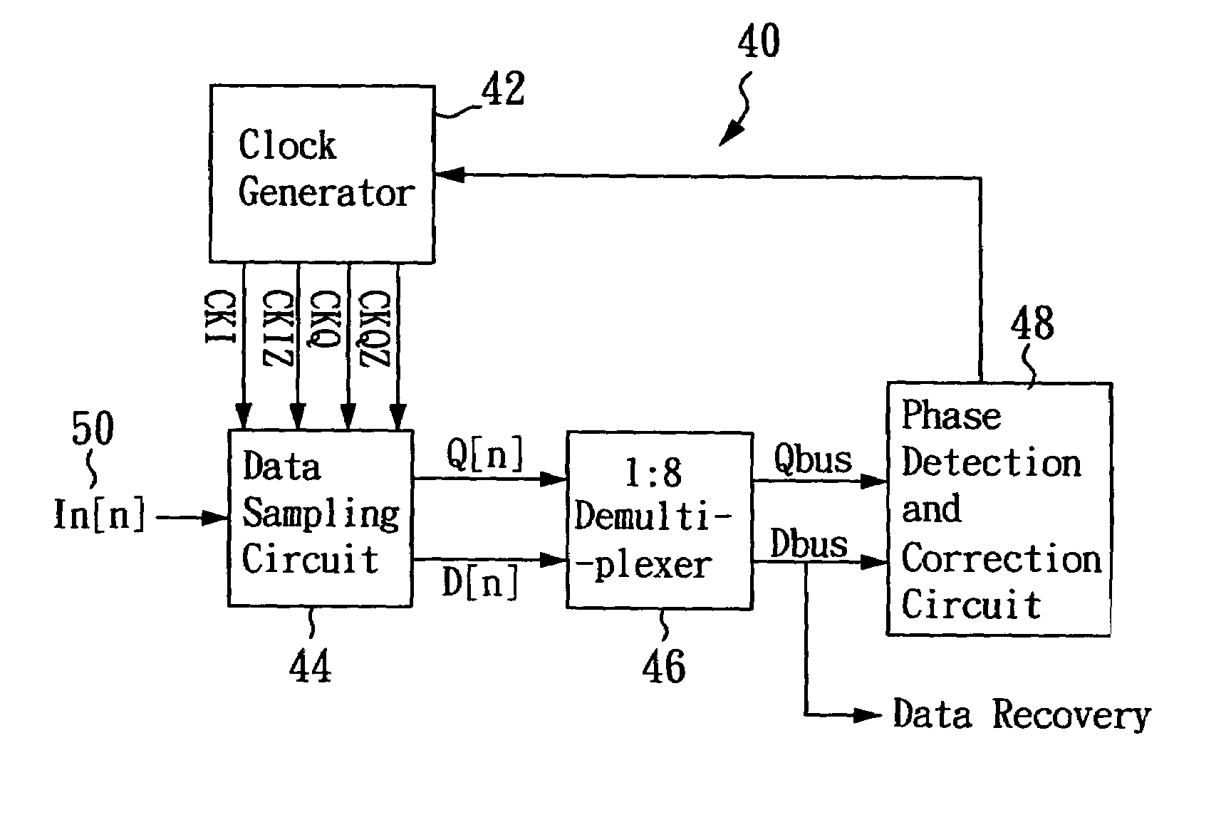
[0023]Please refer to FIGS. 4 and 5, and again to FIG. 1. FIG. 4 shows a schematic block diagram of a preferred embodiment of the data recovery circuit 40 according to the present invention. The data recovery circuit 40 mainly comprises a clock generator 42, a data and phase sampling circuit 44 and a phase detection and correction circuit 48. In addition, the data recovery circuit 40 may further be provided with a demultiplexer 46, coupled between the data and phase sampling circuit 44 and the phase detection and correction circuit 48.

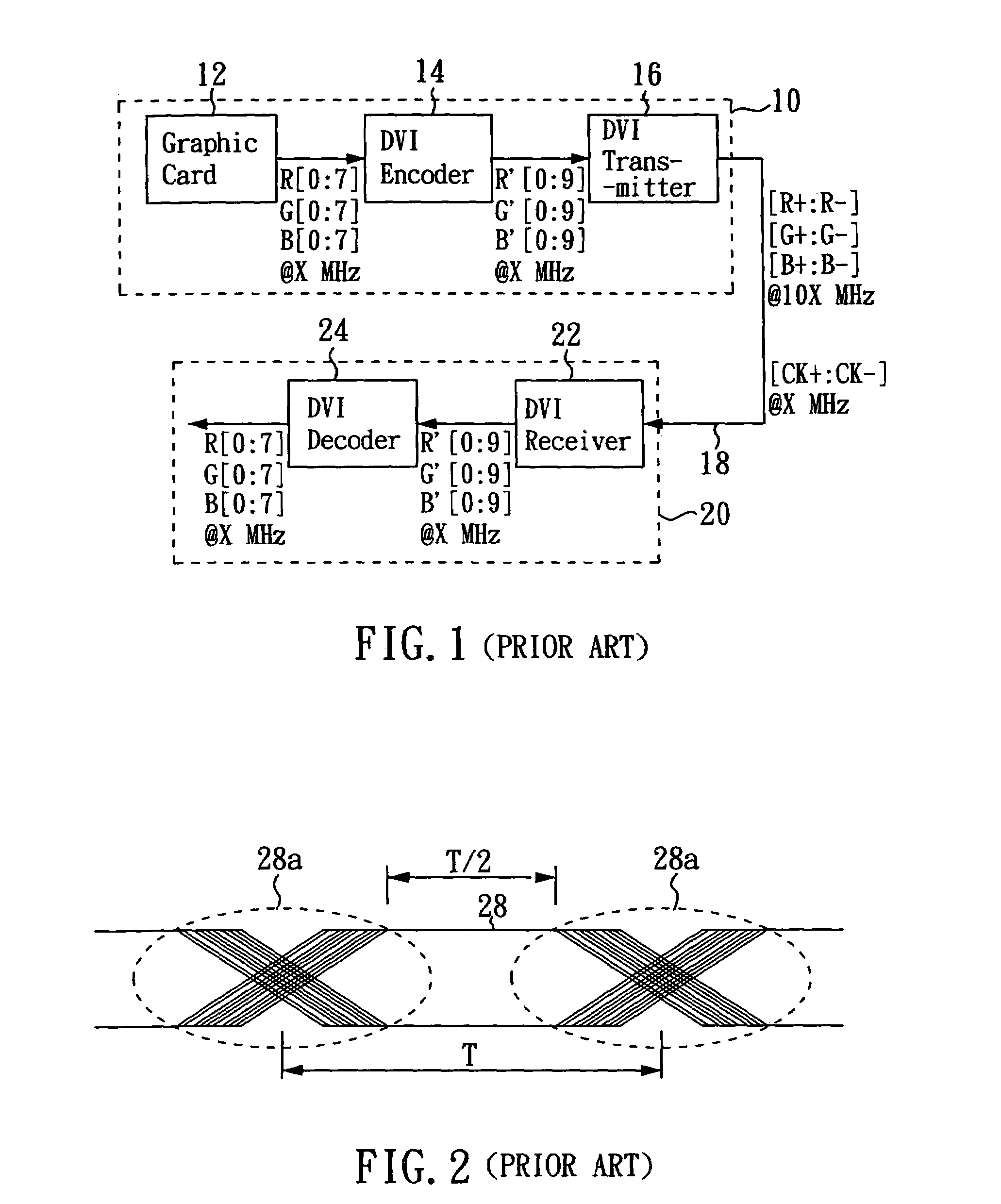
[0024]The differential clock signal [CK+:CK−] transmitted through the DVI transmission cable 18 from the host potion 10 to the display portion 20 in FIG. 1 is coupled to the clock generator 42. From the received differential clock signal (CK+:CK−), the clock generator 42 generates a first group of sampling clock pulses and a second group of sampling clock pulses, each having a frequency at five times the rate of the differential clock signal [CK+:CK−]....


PUM


Abstract

In the data recovery circuit of the invention, a first group of sampling clock pulses is used for sampling approximately the central portions of the data bits in an incoming data stream to produce a first sampled data stream, while a second group of sampling clock pulses is used for sampling approximately the transition portions between every two adjacent data bits in the incoming data stream to produce a second sampled data stream. By detecting the resemblance of each bit in the second sampled data stream to the corresponding two adjacent bits in the first sampled data stream, a phase detection and correction circuit determines an early condition or a late condition for the phases of the sampling clocks and produces a signal to correct the phases of the sampling clocks by shifting the phases backwards or forwards. According to the invention, sampling clocks with lower frequencies can be used for sampling, and the phase error can be corrected to obtain the correct data recovery.

Description

CROSS-REFERENCE TO RELATED APPLICATIONS[0001]This application is based upon and claims the benefit of U.S. provisional application No. 60 / 423,392 filed Nov. 4, 2002, the contents of which are incorporated herein by reference.BACKGROUND OF THE INVENTION[0002]1. Field of the Invention[0003]The present invention relates to a data recovery circuit, and more particularly, to a circuit and a method for minimizing a phase error of a sampling clock in a data recovery circuit.[0004]2. Description of the Related Art[0005]DVI (Digital Visual Interface) is a digital display interface standard established by several PC and graphic card manufacturers. Thanks to the high speed and the excellent display quality of the DVI transmission system, it is foreseeable that DVI interface will become a widely used standard interface for image display in the near future.[0006]FIG. 1 illustrates the data transmission structure of a display system configured with DVI standard. The system mainly comprises a host...

Claims


Application Information

Patent Timeline
Patent Type & Authority Patents(United States)
IPC IPC(8): H04L7/00H04L7/033
CPCH04L7/0331
Inventor SMITH, STERLINGLIU, SHENG-YAOTSAI, HUIMIN
Owner XUESHAN TECH INC
Why Eureka
Try Eureka