System and method for delivering cryogenic fluid

a technology of fluid delivery system and fluid delivery method, which is applied in the direction of manufacturing tools, mechanical equipment, and container discharging methods, etc., can solve problems such as water jet machining problems, and achieve the effect of high pressure and high velocity

Active Publication Date: 2007-12-25
IHI CORP
View PDF16 Cites 83 Cited by
  • Summary
  • Abstract
  • Description
  • Claims
  • Application Information

AI Technical Summary

Benefits of technology

[0005]Embodiments of the invention provide a number of technical advantages. Embodiments of the invention may include all, some, or none of these advantages. For example, in one embodiment, a cryogenic fluid delivery system provides a fluid stream capable of a high pressure and high velocity in order to cut or otherwise machine a wide variety of materials. Such a system may be used in medical applications, such as liver or other types of surgery. By utilizing a cryogenic fluid, such as nitrogen, no secondary waste material needs to be collected; the supercritical nitrogen evaporates shortly after cutting or striking a workpiece. Since nitrogen is present in the atmosphere in substantial quantities, venting into the atmosphere should not pose any problems.

Problems solved by technology

However, water jet machining may suffer from problems relating to the collection of the water during the machining operation or problems relating to the potential contamination of the water or surrounding environment from the material removed from the workpiece.

Method used


Image

  • System and method for delivering cryogenic fluid
  • System and method for delivering cryogenic fluid
  • System and method for delivering cryogenic fluid

Examples


Embodiment Construction

[0018]Embodiments of the present invention and some of their advantages are best understood by referring to FIGS. 1 through 9B of the drawings, like numerals being used for like and corresponding parts of the various drawings.

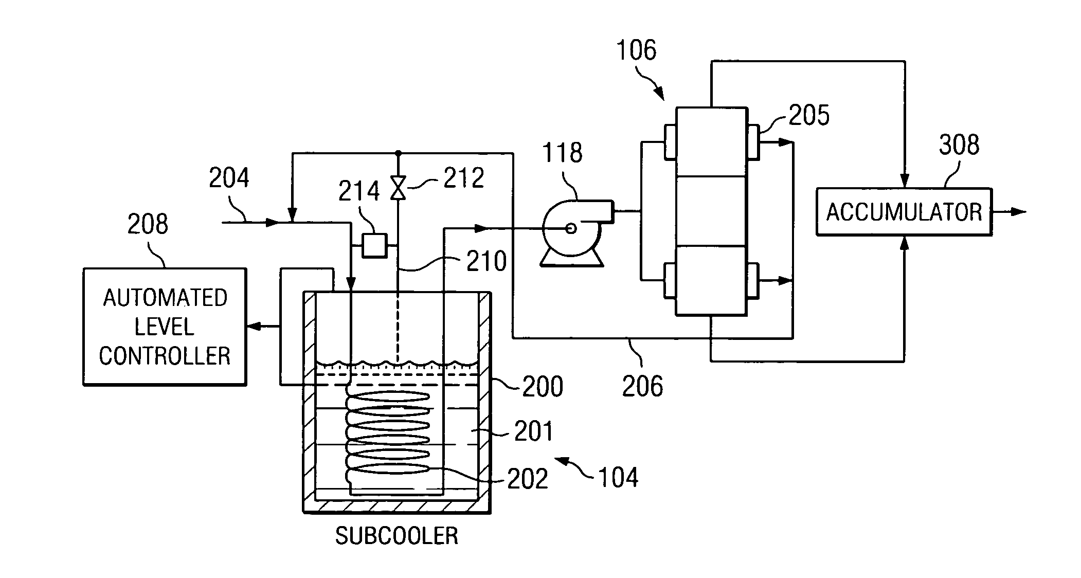
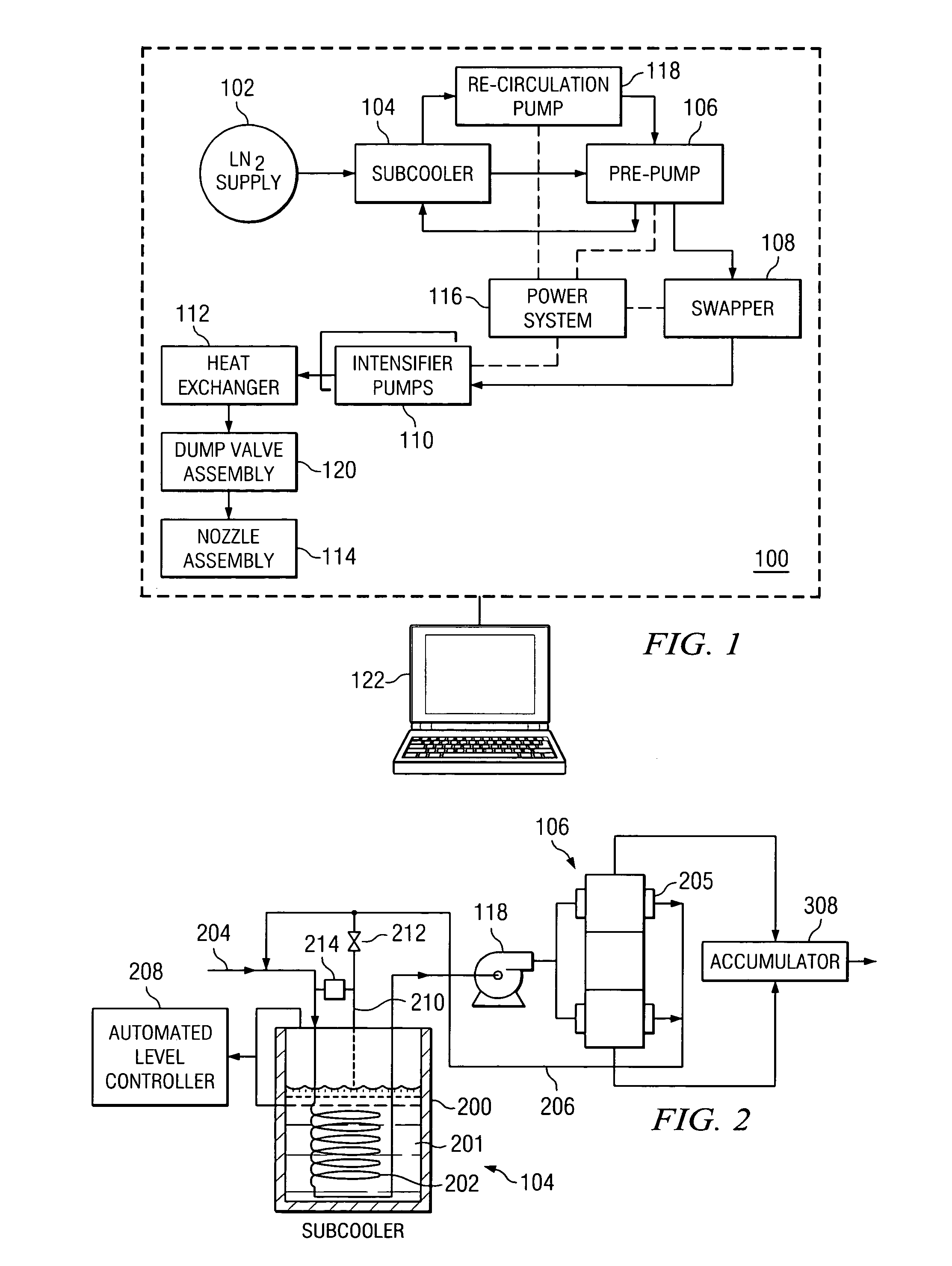
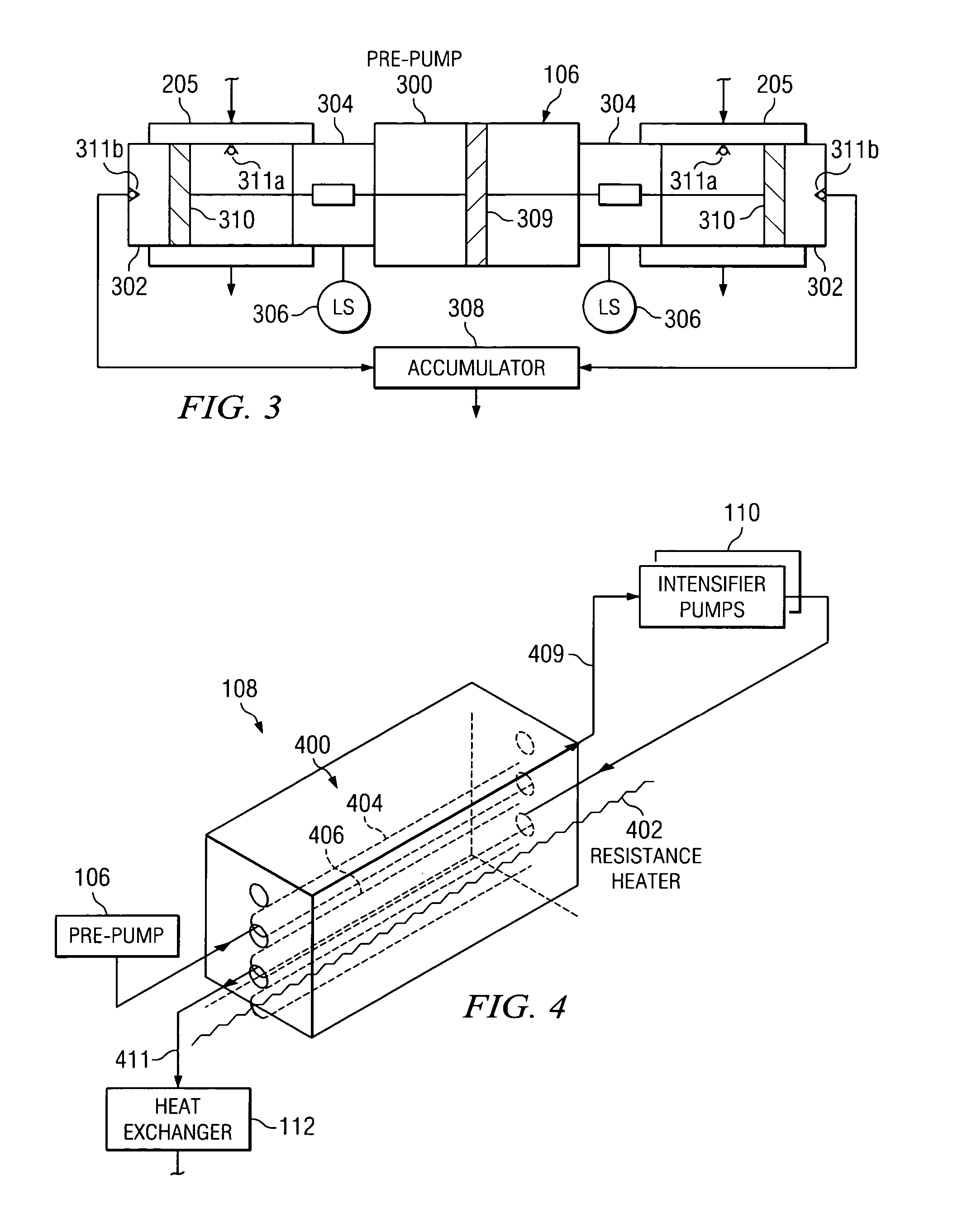
[0019]FIG. 1 is a functional block diagram of a cryogenic fluid delivery system 100 according to one embodiment of the present invention. In the illustrated embodiment, delivery system 100 includes a liquid nitrogen supply 102, a sub-cooler 104, a pre-pump 106, a swapper 108, a pair of intensifier pumps 110, a heat exchanger 112, a nozzle assembly 114, a power system 116, a recirculation pump 118, a dump valve assembly 120, and a controller 122. The present invention, however, contemplates delivery system 100 having more, less, or different components than those illustrated in FIG. 1. Generally, cryogenic fluid delivery system 100 provides a cryogenic fluid stream capable of high pressure and high velocity in order to cut, abrade, or otherwise suitably machine ...


PUM

PropertyMeasurementUnit
pressureaaaaaaaaaa
pressureaaaaaaaaaa
pressureaaaaaaaaaa

Abstract

According to an embodiment of the present invention, a cryogenic fluid delivery system includes a vessel containing a cryogenic fluid at a first pressure and a first temperature, a first heat exchanger coupled to the vessel for receiving the cryogenic fluid and cooling the cryogenic fluid to a second temperature, a first pump coupled to the first heat exchanger for pressurizing the cryogenic fluid to a second pressure, a second pump for pressurizing the cryogenic fluid to a third pressure, a second heat exchanger coupled to the second pump for cooling the cryogenic fluid to a third temperature, and a nozzle coupled to the second heat exchanger for delivering a jet of the cryogenic fluid toward a target.

Description

TECHNICAL FIELD OF THE INVENTION[0001]This invention relates in general to fluid dynamic machining and, more particularly, to a system and method for delivering a cryogenic fluid.BACKGROUND OF THE INVENTION[0002]In fluid dynamic machining the force resulting from the momentum change of the fluid stream is utilized to cut, abrade, or otherwise machine materials. For example, water is often used as a fluid to cut or abrade certain materials and various abrasive materials may be used to enhance material removal. However, water jet machining may suffer from problems relating to the collection of the water during the machining operation or problems relating to the potential contamination of the water or surrounding environment from the material removed from the workpiece.[0003]To address the foregoing problems, sublimable particles, such as dry ice, may be used as the cutting material. The primary advantage of using sublimable particles is that there is no secondary waste material to be ...

Claims


Application Information

Patent Timeline
Patent Type & Authority Patents(United States)
IPC IPC(8): F17C7/02B24B1/00B24C1/00F17C13/00
CPCB24C1/003B24C1/04B24C3/04F17C2270/05F17C2225/0153F17C2270/00
Inventor HUME, HOWARD R.WARNECKE, RONALD R.PALMER, GARY L.FEKETE, LESLIE J.
Owner IHI CORP
Why Eureka
Try Eureka