Coated article having low-E coating with ion beam treated IR reflecting layer and corresponding method

a technology of ion beam and reflective layer, which is applied in the direction of vacuum evaporation coating, coating, water-setting substance layered product, etc., can solve the problems of undesirable drop in visible transmission, undesirable color shift of product, and difficulty in obtaining high visible transmission, so as to improve the ir reflecting characteristics, improve the electric resistance of the ir reflecting layer, and improve the durability of the coated article

Active Publication Date: 2007-12-25
GUARDIAN EURO S A R L +1
View PDF43 Cites 37 Cited by
  • Summary
  • Abstract
  • Description
  • Claims
  • Application Information

AI Technical Summary

Benefits of technology

[0008]In certain example embodiments of this invention, an infrared (IR) reflecting layer(s) is ion beam treated using at least ions from an inert gas such as argon (Ar) and / or Krypton (Kr). It has surprisingly been found that if the ion treatment is performed in a suitable manner, this causes (a) the electrical resistance of the IR reflecting layer to decrease compared to if the ion beam treatment was not performed, thereby improving IR reflecting characteristics thereof, (b) the emittance (e.g., normal) of the IR reflecting layer or coating to decrease compared to if the ion beam treatment was not performed, and / or (c) durability of the coated article to improve.
[0010]Accordingly, suitable ion beam treating of an IR reflecting layer(s) has been found in certain example embodiments of this invention to achieve a combination of: (i) improved resistance of the IR reflecting layer, (ii) improved emittance, (iii) improved solar control characteristics of the coated article such as IR blocking, and / or (iii) improved durability of the coated article.
[0013]In other example embodiments of this invention, the IR reflecting layer may be formed entirely using IBAD. At the beginning of the IR reflecting layer formation using IBAD, the volts applied to the ion source are low or zero so that the ion beam either is not formed or is of a low power type (i.e., low eV per ion). Then, during formation of the IR reflecting layer after at least some of the layer has been deposited, the voltage at the ion source is increased so as to increase the eV per ion in the ion beam. In other words, the ion energy is increased, either progressively or in a step-like manner, during formation of the IR reflecting layer. This prevents or reduces damages to the lower portion of the layer and / or to the layer under the same.

Problems solved by technology

It is often difficult to obtain high visible transmission and adequate solar control properties such as good IR blockage, combined with good durability (chemical and / or mechanical durability) because materials used to improve durability often cause undesirable drops in visible transmission and / or undesirable color shifts of the product upon heat treatment.
However, it has heretofore been difficult to reduce resistance properties (and thus improve IR reflecting characteristics) of an IR reflecting layer without adversely affecting optical characteristics of a coated article (e.g., visible transmission, color, etc.) and / or durability of a coated article.
For instances, significant changes in the thickness of an IR reflecting layer alone may affect resistance, but at the same time may adversely affect durability and / or optical characteristics of the coating.

Method used


Image

  • Coated article having low-E coating with ion beam treated IR reflecting layer and corresponding method
  • Coated article having low-E coating with ion beam treated IR reflecting layer and corresponding method
  • Coated article having low-E coating with ion beam treated IR reflecting layer and corresponding method

Examples


examples

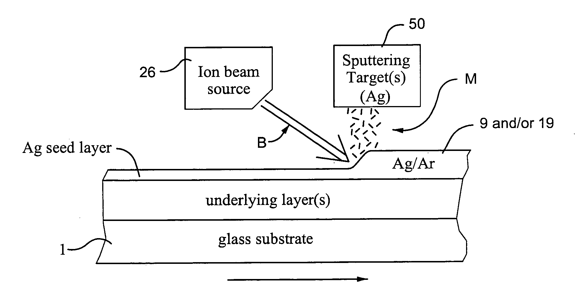
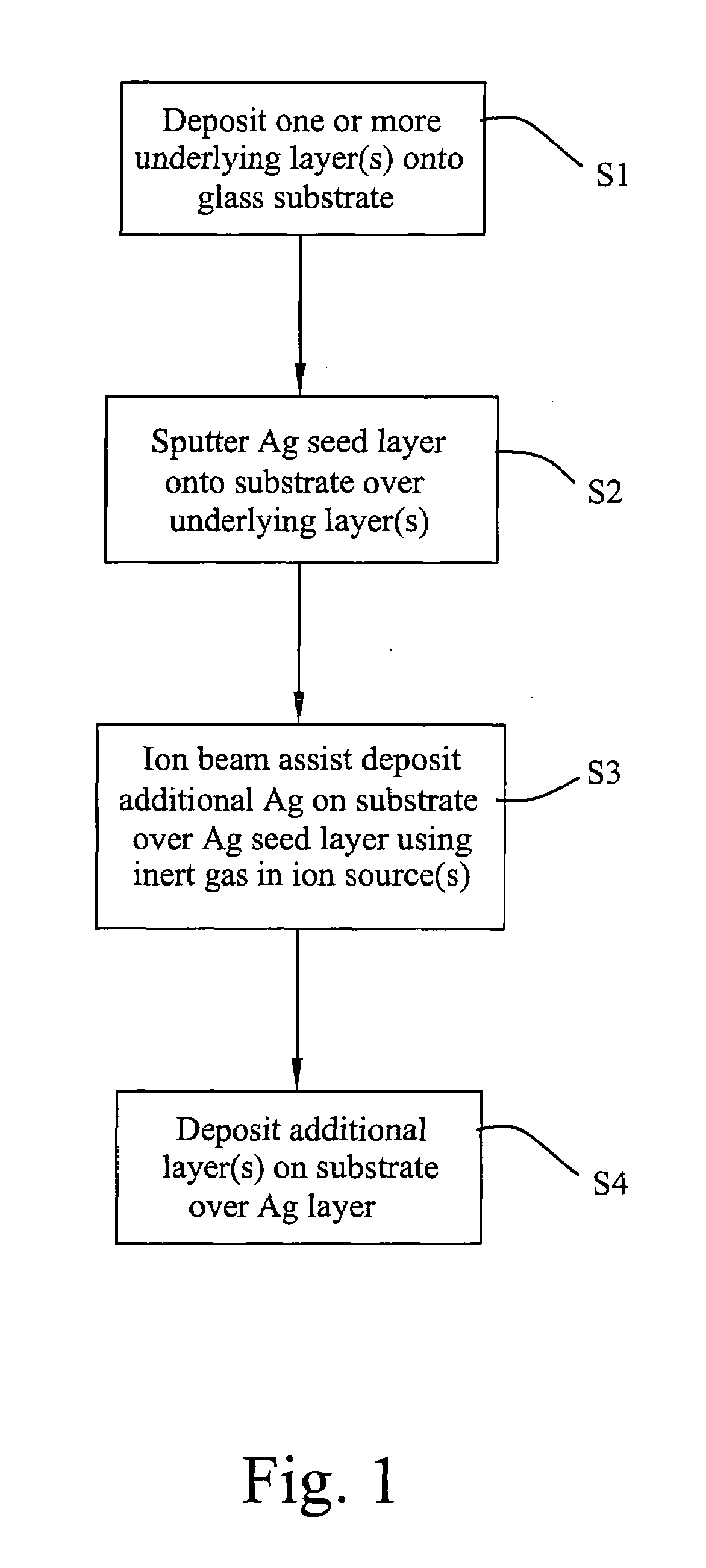
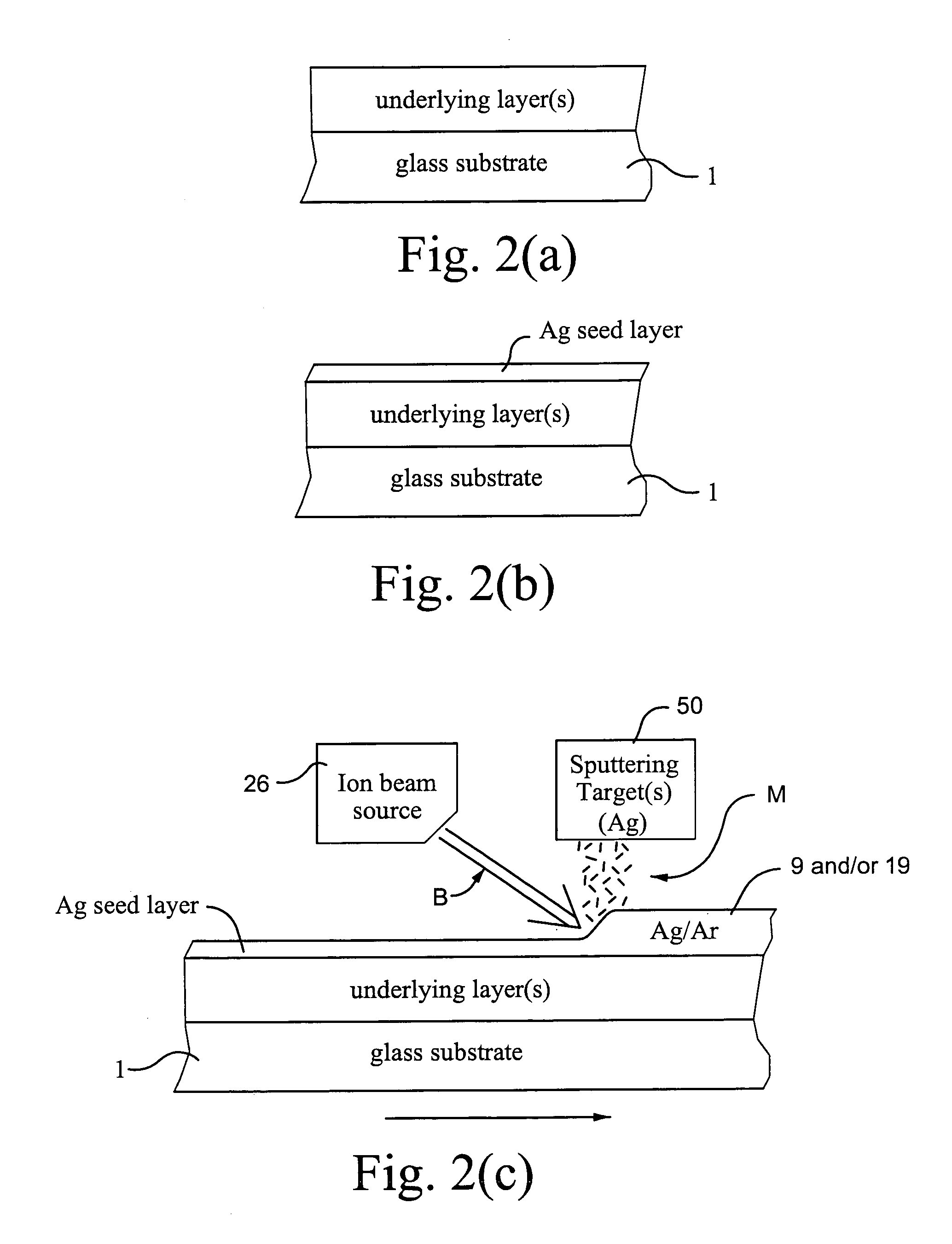
[0069]In Example 1, an IR reflecting layer of Ag was formed on a 100 Å thick ZnO layer. In forming the IR reflecting layer, an Ag seed layer about 60 Å thick was first deposited via sputtering, and thereafter the remainder of the IR reflecting layer was formed using IBAD. The IBAD, at room temperature, utilized a silver sputtering target and an ion beam of argon ions, where the average ion energy was from about 200 to 250 eV per Ar+ ion.

[0070]Comparative Example 1 was the same as Example 1 above, except that the entire Ag IR reflecting layer was formed using only sputtering (no IBAD was used). The results comparing Example 1 and Comparative Example are set forth below.

[0071]

Ex. 1Comparative Ex. 1Ag Thickness (total):120 Å120 ÅSheet Resistance (Rs, ohms / square):3.03.8IBAD:yesnoIon Energy per Ar+ ion:200-250 eV0Stress Type:compressivetensile

[0072]It can be seen from the above that the use of IBAD (see Example 1) in helping form the IR reflecting layer resulted in a significantly impro...

example 6

[0086]Example 6 used post-sputtering peening type of ion beam treatment, and was made and tested as follows. A silicon nitride layer about 425 Å thick was deposited by conventional magnetron-type sputtering using a Si target doped with Al on a substrate. After being sputter-deposited, the silicon nitride layer had a tensile stress of 400 MPa as tested on the quartz wafer. After being sputter-deposited and stress tested, the silicon nitride layer was ion beam treated using an ion source 26 as shown in FIGS. 4-5 under the following conditions: ion energy of 750 eV per N ion; treatment time of about 18 seconds (3 passes at 6 seconds per pass); and N2 gas used in the ion source. After being ion beam treated, the silicon nitride layer was again tested for stress, and had a tensile stress of only 50 MPa. Thus, the post-sputtering ion beam treatment caused the tensile stress of the silicon nitride layer to drop from 400 MPa down to 50 MPa (a drop of 87.5%).

example 7

[0087]The following hypothetical Example 7 is provided for purposes of example only and without limitation, and uses a 2.1 mm thick clear glass substrates so as to have approximately the layer stack set forth below and shown in FIG. 3. The layer thicknesses are approximations, and are in units of angstroms (Å).

[0088]

Layer Stack for Example 7LayerGlass SubstrateThickness (Å)N-doped Si3N4100ZnAlOx109Ag96NiCrOx25SnO2535SixNy126ZnAlOx115Ag95NiCrOx25SnO2127N-doped Si3N4237

[0089]The processes used in forming the coated article of Example 7 are set forth below. The sputtering gas flows (argon (Ar), oxygen (O), and nitrogen (N)) in the below table are in units of sccm (gas correction factor of about 1.39 may be applicable for argon gas flows herein), and include both tuning gas and gas introduced through the main. The line speed was about 5 m / min. The pressures are in units of mbar×10−3. The silicon (Si) targets, and thus the silicon nitride layers, were doped with aluminum (Al). The Zn tar...


PUM

PropertyMeasurementUnit
concentrationaaaaaaaaaa

Abstract

A coated article is provided that may be used as a vehicle windshield, insulating glass (IG) window unit, or the like. An ion beam is used to treat an infrared (IR) reflecting layer(s) of such a coated article. Advantageously, this has been found to improve sheet resistance (Rs) properties, emittance, solar control properties, and / or durability of the coated article.

Description

[0001]This is a continuation-in-part (CIP) of U.S. Ser. No. 10 / 875,515, filed Jun. 25, 2004 now U.S. Pat. No. 7,229,533, the disclosure of which is hereby incorporated herein by reference.[0002]This invention relates to a coated article including a solar control coating such as a low-emissivity (low-E) coating. In certain example embodiments, the low-E coating includes an infrared (IR) reflecting layer(s) of a material such as silver (Ag) or the like which is ion beam treated. In certain example embodiments, the ion beam treatment is performed in a manner so as to cause the IR reflecting layer to realize compressive stress (as opposed to normal tensile stress), and / or to reduce electrical resistance (sheet resistance Rs and / or bulk resistance) and / or emissivity value(s) of the coated article. Coated articles according to certain example embodiments of this invention may be used in the context of vehicle windshields, insulating glass (IG) window units, other types of windows, or in ...

Claims


Application Information

Patent Timeline
Patent Type & Authority Patents(United States)
IPC IPC(8): B32B17/06
CPCB32B17/10036C23C14/586B32B17/10761C03C17/002C03C17/36C03C17/3618C03C17/3626C03C17/3639C03C17/3644C03C17/3652C03C17/366C03C17/3681C03C17/3694C23C14/0652C23C14/185C23C14/3442C23C14/35C23C14/5833B32B17/10174C03C2217/78C03C2218/154C03C2218/32
Inventor BUTZ, JOCHENVEERASAMY, VIJAYEN S.THOMSEN, SCOTT V.DIETRICH, ANTON
Owner GUARDIAN EURO S A R L
Why Eureka
Try Eureka