Embossed cell analyte sensor and methods of manufacture

an analyte sensor and embossed cell technology, applied in the field of analyte sensors, can solve the problems of gumming problems, low printing accuracy, and inability to manufacture repeatable cells at the same size,

Active Publication Date: 2007-12-25
ABBOTT DIABETES CARE INC
View PDF4 Cites 126 Cited by
  • Summary
  • Abstract
  • Description
  • Claims
  • Application Information

AI Technical Summary

Benefits of technology

[0018]Needle and squeegee deposition may take advantage of the volume of a channel already having been defined by an embossing step. The channel and surrounding area may have reagent deposited by the needle dosing system, which is then spread by the squeegee. The squeegee may collect and remove reagent from the flat areas surrounding the channel while leaving the channel fully filled. The wet reagent may then be dried to leave behind a thin film only in the channel. The final coat weight may typically be governed by reagent viscosity, squeegee hardness, squeegee pressure and reagent dilution. The delivery rate of the needle dosing system may be either perfectly balanced to the usage rate or may be in excess with a re-circulation or total loss system employed on the squeegee.
[0019]According to other aspects of the present invention, a process for trimming the ends of the test strips may be provided to calibrate the sensors. After patterning electrodes, embossing, reagent coating and hydrophilic lid lamination as described above, the sensors may essentially be functional. At this stage, pre

Problems solved by technology

A disadvantage of this method is that print registration accuracy and ink rheology limits the smallest size of cell that can be manufactured repeatably.
In addition, three separate processing steps are required, and the mesh and insulation materials are relatively expensive.
A disadvantage of this second method is that gumming problems are often encountered when cutting pressure sensitive adhesives.
Additionally, mechanical punches can only be scaled down to a certain size.
Also, in this process registration is critical in all planes, and the materials used are expensive.
Applying a reagent coating during the manufacture of test strips presents a challenge in situations where pad printing is not suitable.
However, it suffers from a number of problems.
The first problem is that it is a continuous process and therefore coats areas of the web that are not functionally required for the assay.
This not only is wasteful of reagent but also causes variations in height on the sides of the sample chamber, creating problems when sealing the chamber.
If the sample chamber is not well sea

Method used


Image

  • Embossed cell analyte sensor and methods of manufacture
  • Embossed cell analyte sensor and methods of manufacture
  • Embossed cell analyte sensor and methods of manufacture

Examples


Embodiment Construction

[0029]The following description focuses on one variation of the present invention. The variation of the invention is to be taken as a non-limiting example. It is to be understood that the invention is not limited to particular variation(s) set forth and may, of course, vary. Changes may be made to the invention described and equivalents may be substituted (both presently known and future-developed) without departing from the true spirit and scope of the invention. In addition, modifications may be made to adapt a particular situation, material, composition of matter, process, process act(s) or step(s) to the objective(s), spirit or scope of the present invention.

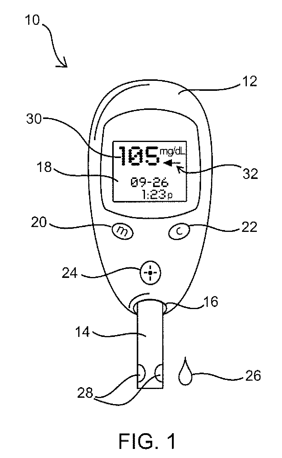
[0030]FIG. 1 shows a top view of an exemplary analyte system 10, a glucometer system in this particular embodiment. System 10 includes a handheld meter 12 and disposable test strip sensor 14. Test strip 14 can be inserted into and removed from test strip port 16 of meter 12 for physical and electrical interconnection therewi...


PUM

PropertyMeasurementUnit
Lengthaaaaaaaaaa
Volumeaaaaaaaaaa
Volumeaaaaaaaaaa

Abstract

An analyte measurement system is provided having sensors with embossed test chamber channels. In one embodiment, the sensors are elongate test strips for in vitro testing, each test strip having a substrate, at least one electrode, an embossed channel in the electrode, and lidding tape covering at least a portion of the embossed channel. Methods of manufacture are also disclosed for filling the sensor channels with reagent, and for trimming the ends of the sensors to eliminate the need for a calibration code during use of the sensors with a meter.

Description

FIELD OF THE INVENTION[0001]The present invention relates to medical devices for monitoring analytes in a living body, such as monitoring glucose levels in people with diabetes. More particularly, the invention relates to an analyte sensor having an embossed sample chamber.BACKGROUND OF THE INVENTION[0002]People with diabetes typically measure their blood glucose level by lancing a finger tip or other body location to draw blood, applying the blood to a disposable test strip in a hand-held meter and allowing the meter and strip to perform an electrochemical test of the blood to determine the current glucose concentration. Such in vitro tests are typically conducted at least several times per day. Detailed descriptions of such glucose monitoring systems and their use are provided in U.S. Pat. No. 7,058,437, issued to TheraSense, Inc. on Jun. 6, 2006, which is incorporated by reference herein in its entirety.[0003]In addition to the examples provided in U.S. Pat. No. 7,058,437, there ...

Claims


Application Information

Patent Timeline
IPC IPC(8): G01N33/53G01M99/00
CPCG01N33/66G01N27/3272A61B5/145C12Q1/006Y10T29/49004Y10T29/49764Y10T436/144444Y10T29/49826Y02P20/582G01N33/487
Inventor PETYT, ADRIANHECTOR, SIMON A.
Owner ABBOTT DIABETES CARE INC
Why Eureka
Try Eureka