Engine brake system of a multicylinder internal combustion engine comprising a cooled intermediate pipe for exchanging gas between cylinders during engine braking

a multi-cylinder internal combustion engine and brake system technology, applied in the direction of machines/engines, combustion air/fuel air treatment, output power, etc., can solve the problems of low achievable brake pressure, low braking output, and dependence on speed, so as to improve heat transmission to the coolant, increase the thermally conductive surface, and increase the cooling capacity

Inactive Publication Date: 2008-01-01
AVL LIST GMBH
View PDF14 Cites 7 Cited by
  • Summary
  • Abstract
  • Description
  • Claims
  • Application Information

AI Technical Summary

Benefits of technology

[0014]It is provided for in a further embodiment of the invention that the at least one cooling fin is twisted in a screw-like manner in the direction of the longitudinal axis of the pressure container. The screw-like twisting of the cooling fin further increases the thermally conductive surface and improves the heat transmission to the coolant. The twisting further increases the swirling in the gas chamber or the coolant chamber. In comparison with a cooling jacket which encloses the tubular pressure container, a considerable increase of the cooling capacity can be effected.
[0015]It can further be provided for within the scope of the invention that the cooling device additionally comprises a cooling jacket penetrated by the coolant, which jacket encloses the tubular pressure container. The cooling capacity and thus the braking power can be increased in an especially high way.
[0016]The cooling pipe or the bundle of cooling pipes is preferably sealed on the coolant side with O-rings. On the gas side, the piston rings protect the O-rings from being directly subjected to the hot braking or exhaust gas.

Problems solved by technology

The disadvantageous aspect in this known system is the dependence on the speed, especially a relatively low braking output in the lower speed range.
The disadvantageous aspect in this motor brake system is, among other things, the relatively low achievable brake pressure.

Method used


Image

  • Engine brake system of a multicylinder internal combustion engine comprising a cooled intermediate pipe for exchanging gas between cylinders during engine braking
  • Engine brake system of a multicylinder internal combustion engine comprising a cooled intermediate pipe for exchanging gas between cylinders during engine braking
  • Engine brake system of a multicylinder internal combustion engine comprising a cooled intermediate pipe for exchanging gas between cylinders during engine braking

Examples


Embodiment Construction

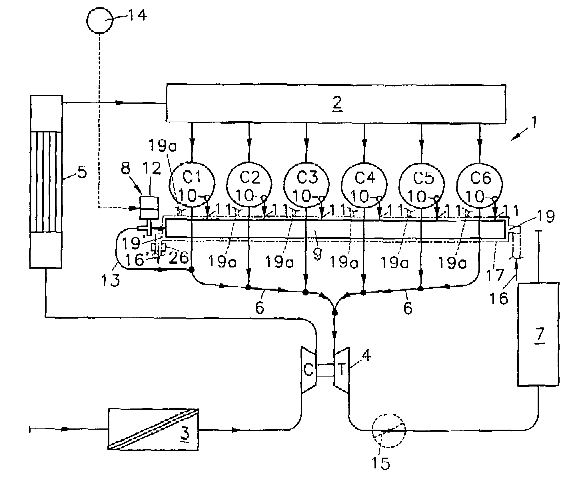
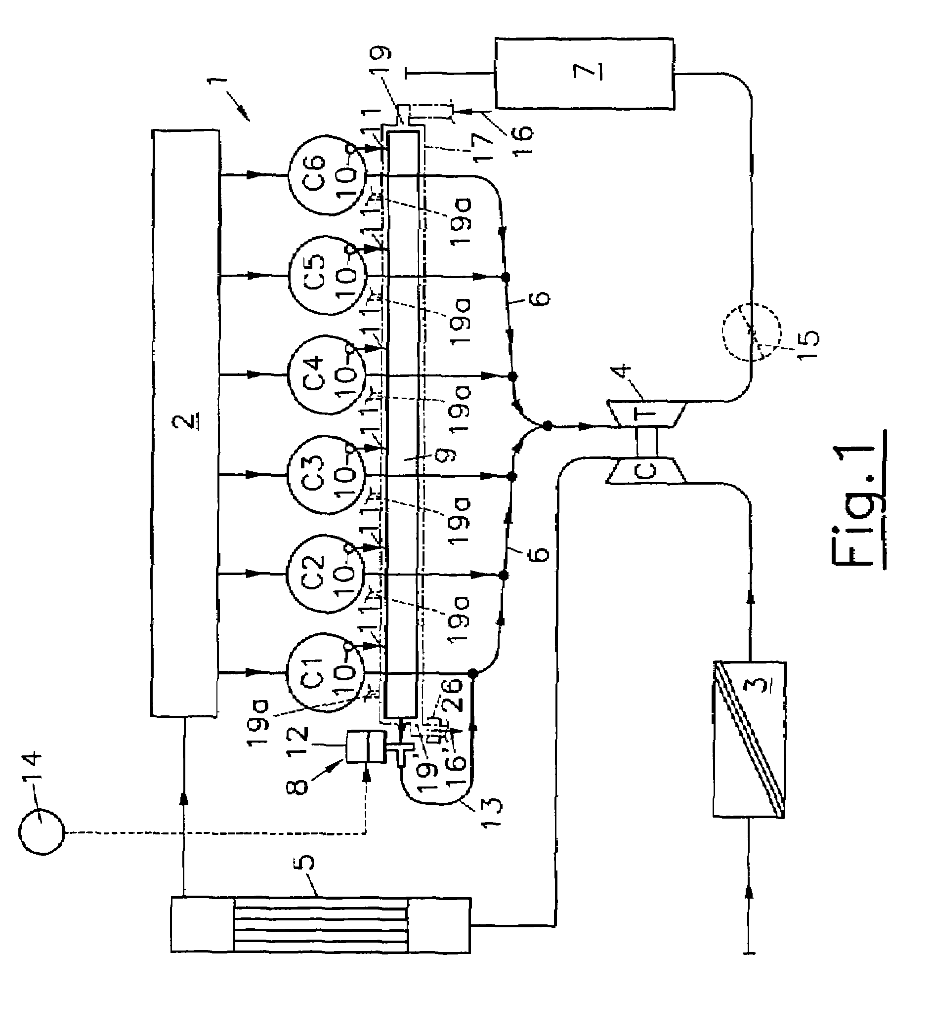
[0035]The invention is explained in detail by reference to FIG. 1 based on the example of a six-cylinder turbocharger engine. Notice must be taken that the function of the engine brake device in accordance with the invention is independent both of the number of cylinders as well as the charging system and can also be used in an aspirating engine.

[0036]The six cylinders C1 to C6 of internal combustion engine 1 are in connection with an intake manifold 2 via intake ports (not shown in closer detail), which intake manifold is supplied with charge air starting from the air filter 3 via the compressor part C of the turbocharger 4 and via the charge air cooler 5. The exhaust valves of the internal combustion engine 1 open into the exhaust system 6, with the exhaust gases being guided in a conventional manner via the turbine part T of the turbocharger 4 and exit via a muffler 7.

[0037]The engine brake device comprises a tubular pressure container 9 (brake rail). Ports 11 originating from th...


PUM


Abstract

The invention relates to a multicylinder internal combustion engine (1) comprising intake valves and exhaust valves that are provided with at least one additional valve (10) for each cylinder (C1, C2, C3, C4, C5, C6), a preferably tubular pressure container (9) with a gas chamber (90) into which extend ducts (11) originating from the valves (10) such that gas can be exchanged between individual cylinders (C1, C2, C3, C4, C5, C6) when the valves (10) are actuated. The pressure container (9) is provided with a device (17) for cooling the quantities of gas exchanged between individual cylinders (C1, C2, C3, C4, C5, C6). In order to increase the cooling capacity, the cooling device (17) encompasses at least one cooling pipe (17) which is axially inserted into the pressure container (9) and is penetrated by coolant. The outer jacket (171) of the cooling pipe (170) borders the gas chamber (90), the gas that is exchanged between individual cylinders (C1, C2, C3, C4, C5, C6) flowing around said outer jacket (171).

Description

BACKGROUND OF THE INVENTION[0001]1. Field of the Invention[0002]The invention relates to a multicylinder internal combustion engine comprising intake valves and exhaust valves which are provided with at least one additional valve for each cylinder, a preferably tubular pressure container with a gas chamber into which extend ducts originating from the valves, so that gas can be exchanged between individual cylinders when the valves are actuated. The pressure container comprises a device for cooling the quantities of gas exchanged between individual cylinders.[0003]2. The Prior Art[0004]Brake systems integrated in vehicle engines, especially in utility vehicles, are gaining increasingly in importance because these systems concern additional brake systems that are cost-effective and compact. The increase in the specific output of modern utility vehicles, however, also requires an increase in the braking power to be achieved.[0005]A four-stroke internal combustion engine with two groups...

Claims


Application Information

Patent Timeline
Patent Type & Authority Patents(United States)
IPC IPC(8): F02D13/04F02M31/00F01L13/06F01N3/04F02B29/04F02B37/00F02D17/02
CPCF01L13/06F01L13/065F01N3/043F02B29/0462F02D13/04F02D17/026F01L2760/004F01N2240/02F02B29/0406F02B37/00Y02T10/146Y02T10/20Y02T10/12
Inventor ROITHINGER, ROBERT
Owner AVL LIST GMBH
Why Eureka
Try Eureka