Electrophotographic photoconductor, electrophotographic process, electrophotographic apparatus, and process cartridge

a photoconductor and electrophotography technology, applied in the direction of electrographic process apparatus, corona discharge, instruments, etc., can solve the problems of low photosensitivity, low image density, inferior image quality, etc., to increase residual potential, reduce charging, and high durability

Inactive Publication Date: 2008-01-01
RICOH KK
View PDF26 Cites 53 Cited by
  • Summary
  • Abstract
  • Description
  • Claims
  • Application Information

AI Technical Summary

Benefits of technology

[0011]The object of the present invention is to provide photoconductors, in which high durability may be achieved, image degradation such as lags may be controlled from the increase of residual potential and decrease of charging, and high quality images may be formed stably even after the prolonged and repeated usage. Furthermore, the object of the present invention is to provide an electrophotographic process, electrophotographic apparatus, and process cartridge for electrophotography, in which the replacements of the photoconductors may be remarkably reduced by virtue of the employment of the inventive photoconductors, the miniaturization of the apparatus may be achieved, and high quality images may be formed stably even after the prolonged and repeated usage.

Problems solved by technology

However, when such organic photoconductors are utilized repeatedly, film scrapings tend to occur; when the film scrapings of the photoconducting layer come to significant, the charging potential of the photoconductor is likely to decrease, the photosensitivity tends to be deteriorated, the background smear comes to apparent due to such flaws on the photoconductor surface, and lower image density and inferior image quality tend to be seriously promoted; as such, the lower wear resistance of the photoconductor has been a serious problem in the art.
However, the smaller and spherical toners have cause such a problem as lower cleaning ability due to the inherently higher mobility, inducing image degradation in terms of the toner filming or fusion, which is a serious problem to be solved.
These proposals are effective by virtue of the decreased friction coefficient initially; however, the cleaning system and the toner should be controlled severely, and the reliability of surface separation is not sufficient under the repeated usage against the degradation or fluctuation of the related parts associated with the prolonged life of the photoconductor.
However, since a large amount of fine particles of the fluorine-contained resin is employed, the compounds exemplified in the application cannot be expected to obtain sufficient effects.
Furthermore, the redox potentials are likely to be lower and variable spontaneously, to form electric traps, and to cause the increase of residual potential.

Method used


Image

  • Electrophotographic photoconductor, electrophotographic process, electrophotographic apparatus, and process cartridge
  • Electrophotographic photoconductor, electrophotographic process, electrophotographic apparatus, and process cartridge
  • Electrophotographic photoconductor, electrophotographic process, electrophotographic apparatus, and process cartridge

Examples


example a

[0295]The present invention will be further explained based on inventive examples and comparative examples, being exemplary and explanatory only, with respect to photoconductors containing the compounds expressed by general formulas (1) to (22) in the protective layer. All percentages and parts are by weight unless indicated otherwise.

[0296]The exemplified compounds incorporated into the protective layers in Example A correspond to the exemplified compounds in terms of each reference No. listed earlier as the specific examples of general formulas (1) to (22).

example a-1

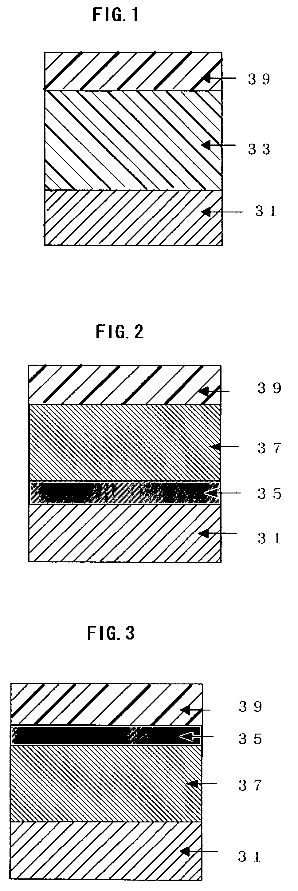
[0297]Coating liquids for under-coating layer, charge-generating layer, and charge-transporting layer having the following compositions respectively, were coated individually by immersion coating and drying in turn on an aluminum cylinder, thereby an under-coating layer of 3.5 μm thick, charge-generating layer of 0.2 μm thick, and charge-transporting layer of 22 μm thick were formed.

-Coating Liquid for Under-Coating Layer

[0298]

Titanium dioxide powder400partsMelamine resin65partsAlkyd resin120parts2-butanone400parts

-Coating Liquid for Charge-Generating Layer

[0299]

Disazo pigment of following formula 12 partsPolyvinyl butyral 5 parts2-butanone200 partsCyclohexanone400 parts

-Coating Liquid for Charge-Transporting Layer

[0300]

Polycarbonate (Z-polyca, by Teijinkasei Co.) 8 partsCharge-transporting substance of following formula 10 partsTetrahydrofuran100 parts

[0301]Coating liquid for protective layer was prepared in the following composition; the coating liquid was readied for coating by c...

example a-2

[0303]Electrophotographic photoconductor 2 was prepared in the same manner as Example A-1, except that the coating liquid for protective layer was changed to following.

-Coating Liquid for Protective Layer

[0304]

Particles of perfluoroalkoxy resin *1)3.3partsDispersion Aid *2)1.0partExemplified compound No. A-3-40.4partPolycarbonate *3)6.4partsTetrahydrofuran200partsCyclohexanone60parts*1) MPE-056, by Mitsui Fluorochemical Co.*2) Modiper F210, by NOF Corporation*3) Z-polyca, by Teijinkasei Co.


PUM


Abstract

The present invention relates to an electrophotographic photoconductor comprising a photoconductive layer, a protective layer, and a conductive support, wherein the protective layer is disposed as the outermost layer of the photoconductive layer, and 20% by volume to 60% by volume of fine particles of fluorine-contained resin and at least one compound selected from amine aromatic compounds and hydroxy aromatic compounds are incorporated into the protective layer.According to the present invention, high durability may be achieved, image degradation such as lags may be controlled from the increase of residual potential and decrease of charging, and high quality images may be formed stably even after the prolonged and repeated usage.The present invention also relates to an electrophotographic process, an electrophotographic apparatus and a process cartridge for the electrophotographic apparatus which utilize the electrophotographic photoconductor respectively.

Description

BACKGROUND OF THE INVENTION[0001]1. Field of the Invention[0002]The present invention relates to an electrophotographic photoconductor with high durability and high image quality. The present invention also relates to an electrophotographic process, an electrophotographic apparatus and a process cartridge for the electrophotographic apparatus which utilize the electrophotographic photoconductor respectively.[0003]2. Description of the Related Art[0004]In recent years, information processing systems have achieved remarkable advance along with the progress of the related apparatuses employing electrophotography. In particular, laser printers and digital copiers have significantly enhanced the printing quality and reliability in which the image recordings of them are conducted based on lights through transferring information into digital signals. In addition, the information processing systems have been applied progressively to laser printers and digital copiers capable of full-color p...

Claims


Application Information

Patent Timeline
Patent Type & Authority Patents(United States)
IPC IPC(8): G03G5/047G03G5/06G03G5/147G03G13/00G03G15/00
CPCG03G5/14708G03G5/061473G03G5/06144G03G5/06147G03G5/06145G03G5/061443G03G5/06142
Inventor IKEGAMI, TAKAAKINOHSHO, SHINJIKURIMOTO, EIJIKAMI, HIDETOSHISUGINO, AKIHIROYAMASHITA, YASUYUKINAKAMORI, HIDEOTAKADA, TAKESHI
Owner RICOH KK
Why Eureka
Try Eureka