Interpupillary distance adjustment mechanism for optical device

an optical device and interpupillary technology, applied in the field of interpupillary distance adjustment mechanism of optical devices, can solve the problems inconvenient carrying, and inability to adjust the distance of the optical device, so as to prevent the movement of the slide block along the slide rail, prevent the movement of the slide block relative to the slide rail, and prevent the effect of unfavorable monocular laser rangefinder viewing

Inactive Publication Date: 2008-01-01
ASIA OPTICAL CO INC
View PDF16 Cites 4 Cited by
  • Summary
  • Abstract
  • Description
  • Claims
  • Application Information

AI Technical Summary

Benefits of technology

[0010]The main object of the present invention is to provide an interpupillary distance adjustment mechanism for an optical device, especially for a laser rangefinder, which allows the user to manually adjust the distance between the lens barrels during use of the optical device, so as to accommodate different user interpupillary distances.
[0011]Another object of the present invention is to provide an interpupillary distance adjustment mechanism for an optical device, especially for a laser rangefinder, which allows the user to manually adjust the degree of looseness and tightness of the sliding movement of the lens barrels and to fix the distance between the lens barrels when viewing.
[0012]To achieve the above objects of the present invention, an interpupillary distance adjustment mechanism for an optical device in accordance with the present invention comprises a slide rail mounted on a middle support of the optical device, two slide blocks mounted on respective lens barrels of the optical device, and a blocking member. The two slide blocks are slidably movable relative to the slide rail toward or away from each other to change the distance between the two lens barrels of the optical device. The blocking member is manually operable to provide an acting force between one slide block and the slide rail and thus change the friction force therebetween during sliding movement of the slide block. In this way, undesired sliding movement of the slide block relative to the slide rail can be prevented.
[0015]Alternatively, the interpupillary distance adjustment mechanism for an optical device in accordance with the present invention may also be configured to comprise a slide rail mounted on one lens barrel of the optical device, a slide block mounted on the other lens barrel of the optical device, and a blocking member. The slide block is slidably movable along the slide rail to change the distance between the two lens barrels of the optical device. The blocking member is manually operable to provide an acting force between the slide rail and the slide block and thus change the friction force therebetween during sliding movement of the slide block. In this way, undesired sliding movement of the slide block relative to the slide rail can be prevented.
[0016]By the relative movement between the slide rail and the slide block, the distance between the two lens barrels of the optical device can be changed, and thus different user interpupillary distances can be accommodated. By further employing a blocking member, which is in the form of a friction block or the combination of a magnet and an interrupter, to provide the normal force and thus adjust the friction force between the slide rail and the slide block during sliding movement of the slide block, further sliding movement of the slide block along the slide rail can be prevented. Accordingly, the distance between the lens barrels is fixed, and undesired movement of the lens barrels during viewing is thus efficiently prevented.

Problems solved by technology

However, the monocular laser rangefinder is generally very long in size, which is inconvenient for carry.
Further, monocular viewing of the target object is much more tiring for the human eye than binocular viewing.
However, it has the disadvantage that miniaturization design is difficult.
However, after long time use, it is possible that the torque setting screws become loose.
Consequently, the torque of the slide rail is decreased, and the two lens barrels may be caused to move relative to each other upon inclination, thereby resulting in undesired change of interpupillary distance.
This makes it difficult for the user to manually adjust the torque of the torque setting screw.

Method used


Image

  • Interpupillary distance adjustment mechanism for optical device
  • Interpupillary distance adjustment mechanism for optical device
  • Interpupillary distance adjustment mechanism for optical device

Examples


first embodiment

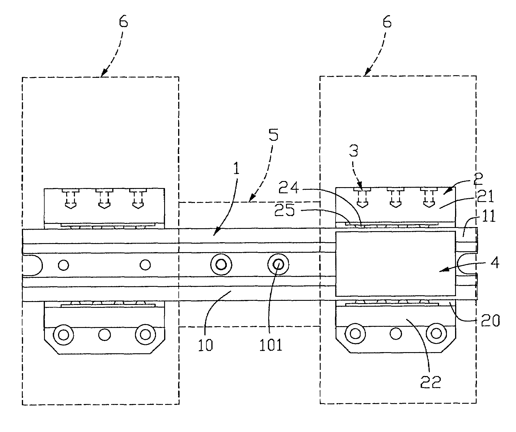
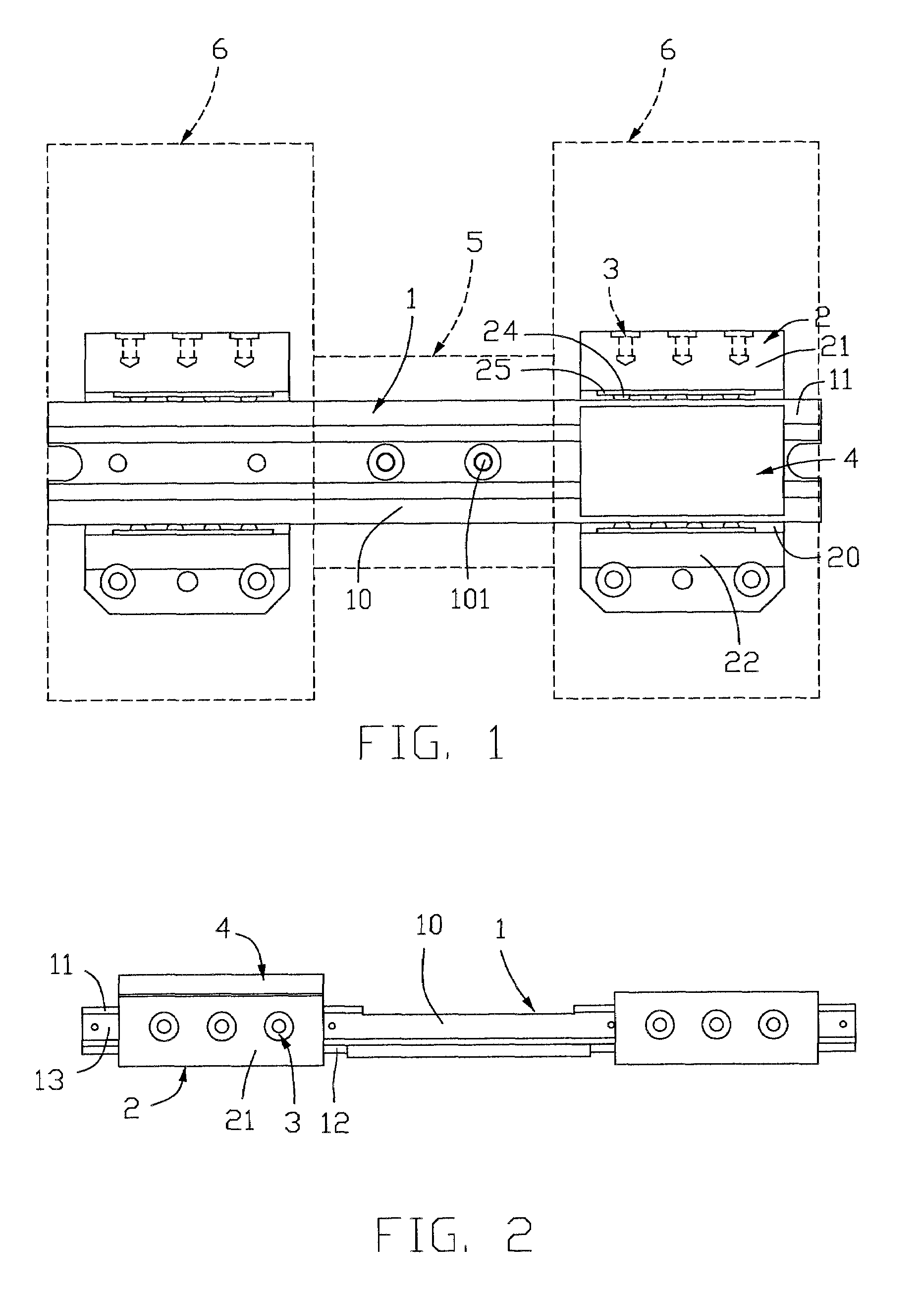
[0023]Referring to FIG. 1, an interpupillary distance adjustment mechanism for an optical device in accordance with the present invention comprises a slide rail 1, a pair of slide blocks 2 movably mounted on the slide rail 1, and a blocking member 4. The slide rail 1 comprises a middle mounting portion 10 and two track portions 11 at opposite ends of the mounting portion 10. Two mounting holes 101 are defined in the mounting portion 10 for extension of two screws therethrough, so as to mount the slide rail 1 on a middle support 5 (shown in dashed lines) of a binocular optical device. As clearly shown in FIGS. 2 and 3, a pair of cylindrical guide posts 12 is received in the bottom of each track portion 11 of the slide rail 1. A rectangular guide slot 13 is defined in each side of the track portion 11.

[0024]Each slide block 2, which is substantially U-shaped, comprises a recess 20 and a pair of side portions 21, 22 on opposite sides of the recess 20. A pair of receiving slots 200 (sho...

second embodiment

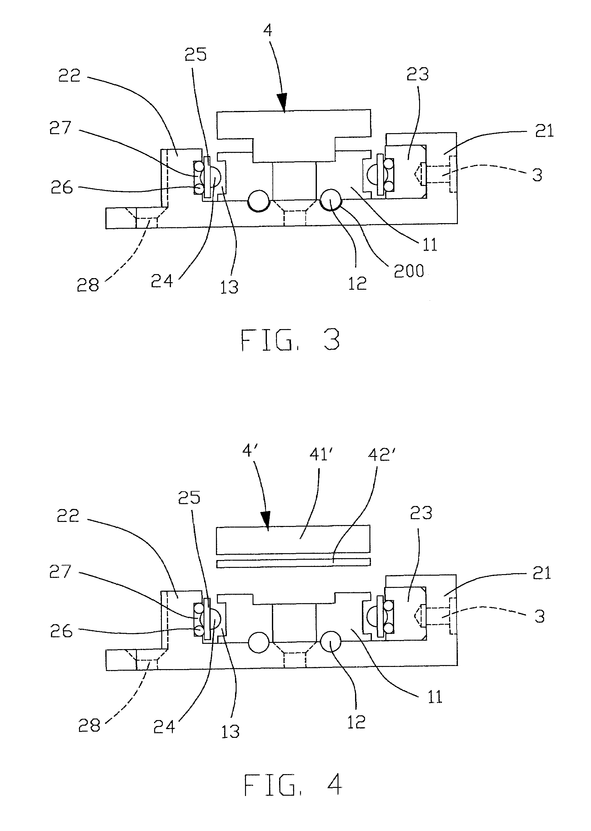
[0026]FIGS. 4 and 5 illustrate an interpupillary distance adjustment mechanism for an optical device in accordance with the present invention. In this embodiment, the blocking member, which is designated with reference numeral 4′ for distinction, comprises a magnet 41′ disposed above one of the two track portions 11 of the slide rail 1, and an interrupter 42′ arranged between the magnet 41′ and the track portion 11. The magnet 41′ is preferably a strong magnet, such as an Nd—Fe—B magnet. The interrupter 42′ is made of non-magnetic materials, such as aluminum, brass or bronze. Alternatively, the interrupter 42′ may be a reverse magnet, such as a rubber magnet, which generates reverse magnetic force to partially counteract the strong magnetic force of the magnet 41′. The rubber magnet is made from rubber materials such as cured nitrile rubber as binder containing barium ferrite magnet particles. The rubber magnet is flexible, and uneasy to break and crack against shock. Therefore, it ...


PUM


Abstract

An interpupillary distance adjustment mechanism for an optical device includes a slide rail (1) mounted on a middle support of the optical device, two slide blocks (2) mounted on respective lens barrels of the optical device, and a blocking member (4, 4′). The two slide blocks are slidably movable relative to the slide rail toward or away from each other to change the distance between the two lens barrels of the optical device. The blocking member is manually operable to provide an acting force between the slide block and the slide rail, and thus changing the friction force therebetween during sliding movement of the slide block. In this way, undesired sliding movement of the slide block relative to the slide rail can be prevented.

Description

BACKGROUND OF THE INVENTION[0001]1. Field of the Invention[0002]The present invention relates to an interpupillary distance adjustment mechanism for an optical device, and particularly to an interpupillary distance adjustment mechanism that is manually operable during use of the optical device.[0003]2. Description of Prior Art[0004]A laser rangefinder is one of the main optical devices for distance measurement. A common type of laser rangefinder usually applies a laser emitter as a light source for transmitting a modulated laser light beam to a target object to be measured. The target object reflects and returns the laser light beam to a laser receiver. The distance to the target object is determined by multiplying the light velocity by the time interval between emission of the laser beam and the receipt of the reflected beam, and can be expressed as: L=C*Td / 2, wherein “L” represents the distance between the target object and the laser rangefinder, “C” represents the light velocity,...

Claims


Application Information

Patent Timeline
Patent Type & Authority Patents(United States)
IPC IPC(8): G02B23/00G02B27/02
CPCG02B7/12G02B23/18
Inventor SHIH-YU, PAIHSIANG-YI, LAI
Owner ASIA OPTICAL CO INC
Why Eureka
Try Eureka