Apparatus, system and methods for collecting position information over a large surface using electrical field sensing devices

a technology of electrical field sensing and apparatus, applied in the direction of speed measurement using gyroscopic effects, gyroscope/turn-sensitive devices, instruments, etc., can solve the problems of limited number of objects that can be tracked simultaneously, difficult calibration of these systems, and inability to always be possible, so as to reduce maintenance and minimize set-up time

Inactive Publication Date: 2008-01-01
JEAN PHILIPPE
View PDF4 Cites 69 Cited by
  • Summary
  • Abstract
  • Description
  • Claims
  • Application Information

AI Technical Summary

Benefits of technology

[0018]It is another object of the invention to provide a means for tracking a large number of objects, typically in excess of twelve, simultaneously on a surface such as a theatre stage. Accordingly, the present invention addresses the need to increase the number of objects that can be tracked simultaneously over a large surface. A multi sub-controller configuration can typically feature up to one hundred sensing tiles and more for providing a coherent sensing surface area of up to 225 sq meter and more. Such sensing surface can capture the position of typically up to thirty persons, at a resolution per point in the range of ten sq cm.
[0019]It is yet another object of the invention to provide a reliable tracking system over a large surface such as a theatre stage that necessitates minimal set-up time. This object is achieved by the use of a capacitance sensing surface, which avoids the need for the persons or objects to either wear a transmitter, an emitter, or a visible mark. The sensing surface is being embedded in a floor or on other surfaces, in whole or in part, and its operation is not affected by changes in setting or replacement of objects.
[0020]It is another object of the invention to provide a tracking system over a large surface such as a theatre stage that provides a long useful life and that necessitate reduced maintenance. Maintenance of the sensing surface is limited to the replacement of faulting individual sensing tiles, tile controllers, sub-group or group controller or cabling, without affecting the functioning of other elements of the sensing surface. The use of low power consumption capacitance sensing tiles and the use of inert and robust substrate for the construction of the sensing tiles limit component's wear and tear at minimum.
[0021]In an advantage, the invention is of particular utility when used to collect position and movement information of persons and objects over a large surface such as a theatre stage, cinema and television studios, retail stores, exhibition spaces and locations of the like.

Problems solved by technology

Calibration of these systems can be difficult, especially when the objects are positioned in the vicinity of reflective surfaces.
Another set back or these systems is the limited number of objects that can be tracked simultaneously due to restrictions on available bandwidth for such systems.
This system requires that each projector be coupled to an infrared TV camera and an electrically powered yoke or turntable, and that the object wears a mark that must remain visible at all times by a camera for the system to be effective, which is not always possible, particularly when setting elements are located on stage.
Since most of these technologies use projective row and columns sensors which integrate on one electrode the proximity of all objects in a particular row or column, they cannot uniquely determine the positions of two or more objects.
The arrangement taught in U.S. Pat. No. 6,323,846 B1 does not permit a fully modular construction of the sensing devices, which modularity is required to cover large surfaces at reasonable manufacturing cost, and to enable an easy error-detection or default detection, and maintenance over a long useful life, in form of replacement of defaulting sections.

Method used


Image

  • Apparatus, system and methods for collecting position information over a large surface using electrical field sensing devices
  • Apparatus, system and methods for collecting position information over a large surface using electrical field sensing devices
  • Apparatus, system and methods for collecting position information over a large surface using electrical field sensing devices

Examples


Embodiment Construction

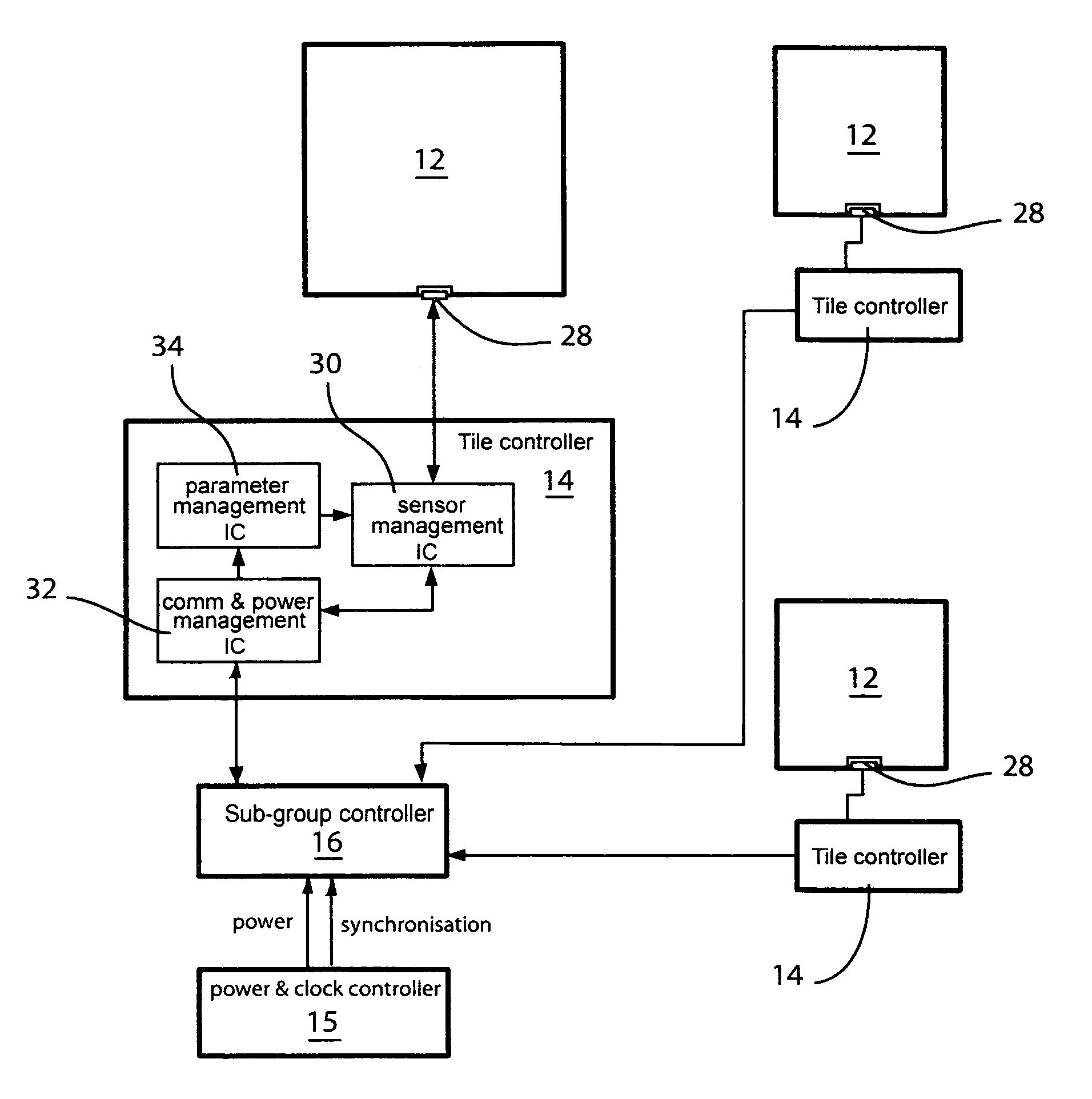
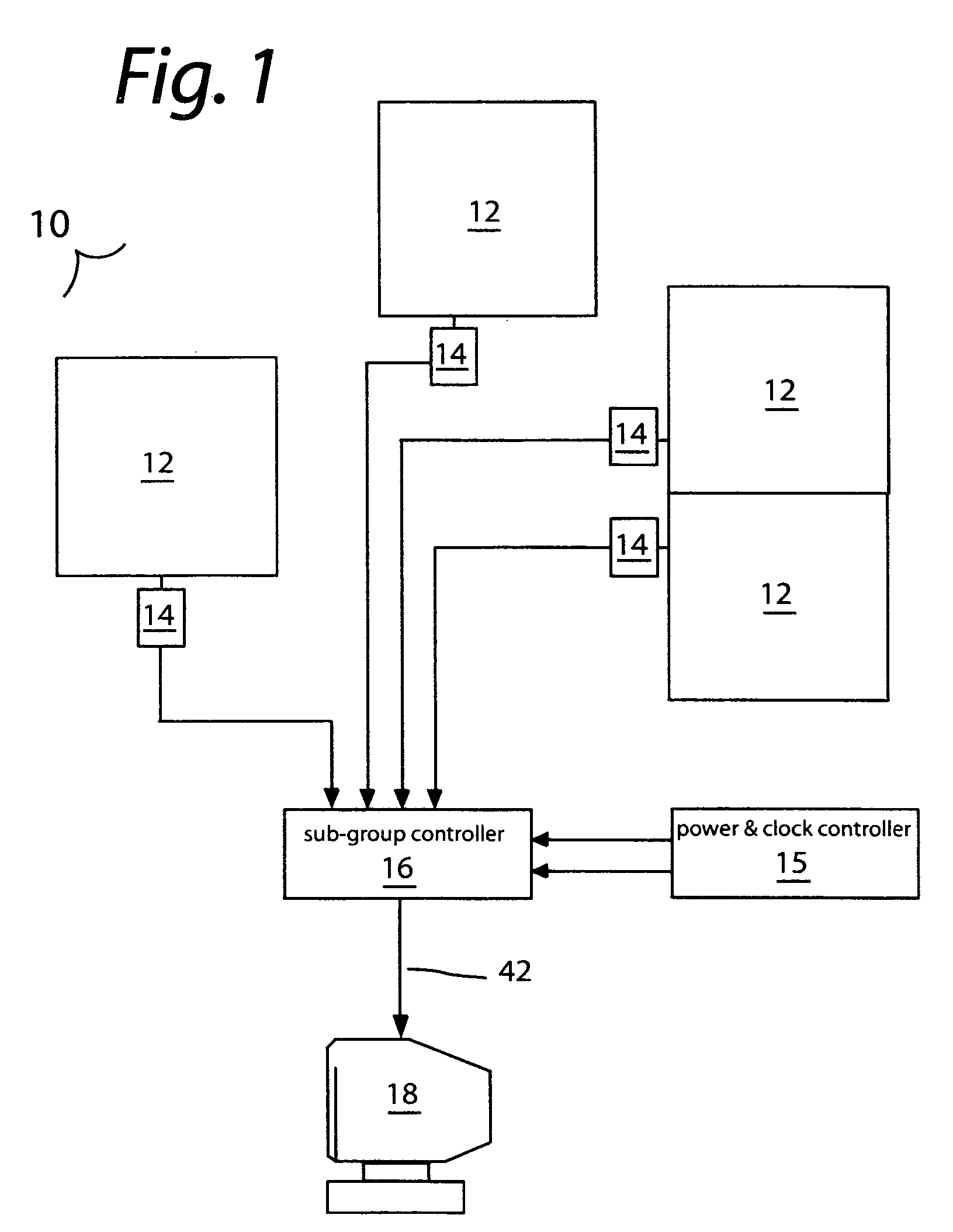
[0033]Referring to the Figures, wherein like numerals indicate like or corresponding parts throughout the several views, a system for collecting information on the geographic position of several objects simultaneously over a large surface using electrical field sensing devices is generally indicated at 10 (“sensing surface”). The sensing surface system 10 and preferred embodiment of the present invention illustrated at FIG. 1 comprises a plurality of not-necessarily adjacent sensing tiles 12 that are sensitive to changes in self-capacitance brought about by changes in proximity or contact with an object to the sensing tile 12, tile controllers 14, a power and clock controller 15 and a sub-group controller 16 that connects a sub-group of several sensing tiles 12 by their respective tile controller 14 in order to form a coherent sensing surface for the collection and reconnaissance of positioning and movement information, and a central computer or client system 18 for using the sensin...


PUM


Abstract

An apparatus, system and methods are provided for collecting information on the geographic positions of several moving or immobile objects simultaneously. A plurality of large scale printed circuits having charge transfer capacitance sensing properties are linked by a communication network in order to form a coherent sensing surface for the collection and reconnaissance of positioning and movement information. The positioning and movement information gathered can be used as input information by media control systems.

Description

FIELD OF THE INVENTION[0001]The present invention relates generally to methods and apparatus for data input and for tracking objects, and in particular for input and tracking objects such as a person or a ball automatically for the purpose of, for example lighting up the vicinity of objects throughout their displacement over a surface.BACKGROUND OF THE INVENTION[0002]Related art shows several methods and apparatus used for collecting position information that can be used in conjunction with audio-visual systems to provide automatic follow-spot and other audio-visual applications in theatre stage, cinema and television studios, retail stores, exhibition spaces and locations of the like. Several such methods and apparatus are based on systems for the triangulation of sound waves or radio waves. These systems require that an emitter or, for other systems a receptor, be placed at all times on the object of which position information is collected. Calibration of these systems can be diff...

Claims


Application Information

Patent Timeline
Patent Type & Authority Patents(United States)
IPC IPC(8): G06F19/00
CPCH05B37/0227H05B37/029H05B47/125H05B47/155Y02B20/40
Inventor JEAN, PHILIPPE
Owner JEAN PHILIPPE
Why Eureka
Try Eureka