
Methods and apparatus for managing network resources using a network topology view

a network topology and network management technology, applied in the field of computer and software systems, can solve the problems of software applications and computerized devices, each of these conventional techniques for displaying a network topology or interconnection of manageable network resources suffer from deficiencies, and achieve the effect of quick determination of zone configuration

Active Publication Date: 2008-01-01
EMC IP HLDG CO LLC
View PDF1 Cites 245 Cited by
  • Summary
  • Abstract
  • Description
  • Claims
  • Application Information

AI Technical Summary

Benefits of technology

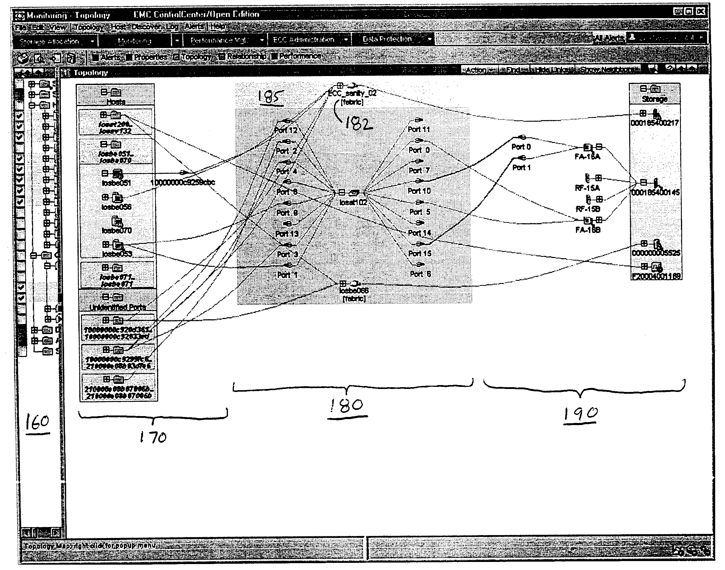
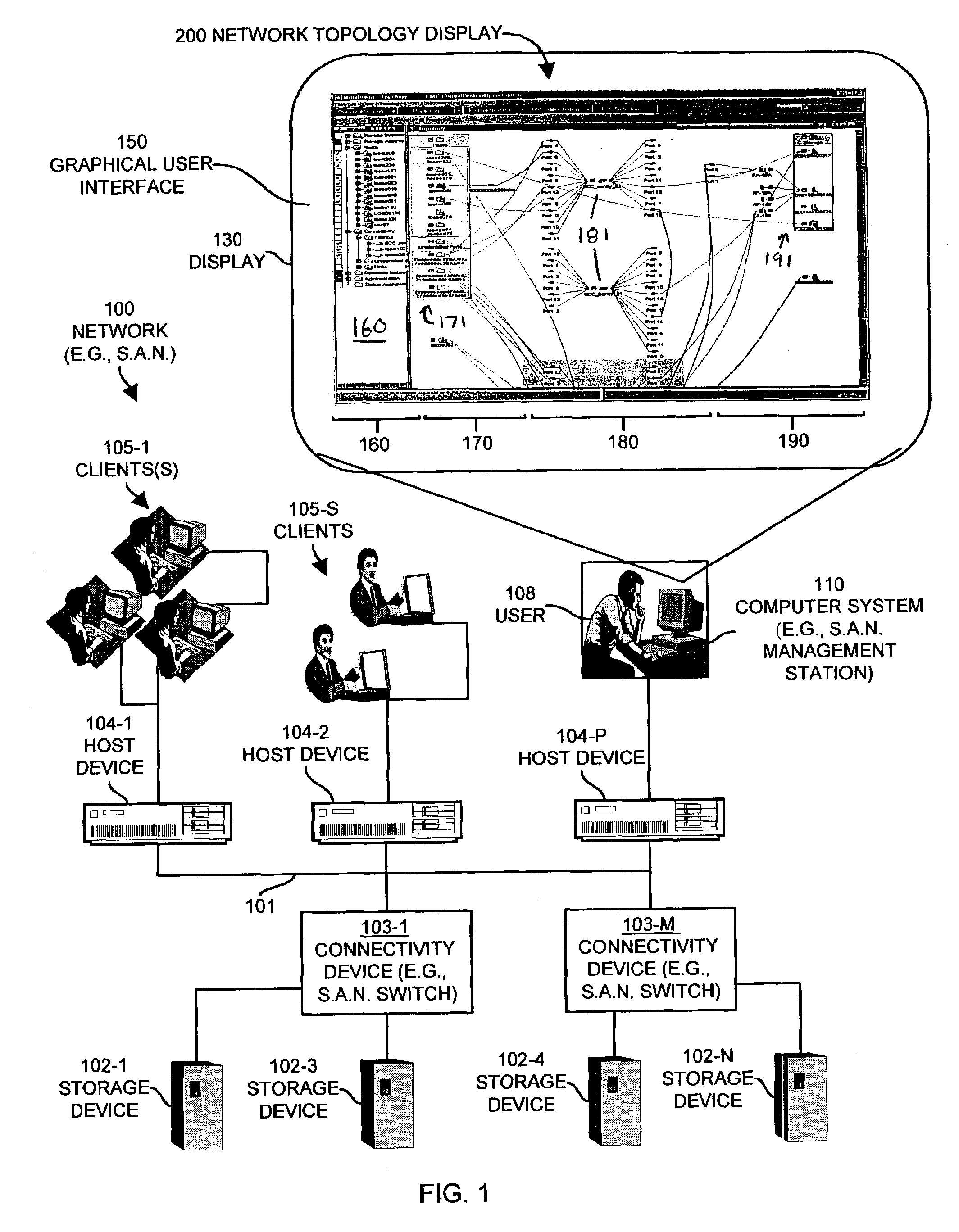
[0013]Embodiments of the invention further operate to display the coupling condition, for example as a graphical line or link on the display of the computerized device, between the connectivity element and either or both of the host element and the storage element to which that coupling condition relates in order to visually convey the coupling condition to a user viewing the network topology view. In other words, embodiments of the invention can determine coupling conditions between managed network resources and can then visually display or represent these coupling conditions, for example, as graphical lines drawn or otherwise rendered within the network topology view between the displayed host, connectivity and storage elements displayed within the respective display areas. Since the host display area is separated from the storage display area by the connectivity display area, this processing creates the effect of displaying data communications links between displayed elements from one display area (e.g., a host element representing a host computerized device in the host display area) to another display area (e.g., a connectivity element representing a switch in a connectivity display area). Since elements of each type (e.g., host, connectivity and storage) are maintained in respective areas, the user can quickly determine, for example, which icons correspond to host related devices, switch or connectivity device, storage devices and so forth.
[0016]Further still, since the user may select managed resources to be included or excluded from the network topology view and the embodiments of the invention always add or remove these resources from the respective display areas according to the selected resource type, the user does not have to visually hunt through the network topology view in an attempt to locate a resource that has been selected for viewing within the network topology view. Rather, since embodiments of the invention provide the respective display areas broken down into different resource types (e.g., host display area, connectivity display area, storage display area), the user will intuitively know where to look to further invoke management operations on a resource that is selected by that user to be included within the network topology view.
[0017]In addition to the aforementioned embodiments of the invention, other embodiments of the invention provide refinements and additional features based upon the aforementioned network topology view framework. As an example, a user is able to operate embodiments of the invention to create user-defined groups of managed resources and is then able to expand and collapse these groups within the network topology view. Embodiments of the invention further provide various unique group control mechanisms that allow for ease of use to expand and collapse groups and to add and remove a particular resource or resources from a particular group.
[0018]Further still, other embodiments of the invention provide automatic alignment of elements within the network topology view as a user adds or removes resources into or out of the view or when a user expands a particular resource in a view to see managed resource elements related to that particular resource. In particular, certain embodiments of the invention include a concept of parent-child relationships between elements displayed within the network topology view. As an example, consider a host computerized device that includes a number of host bus adapter devices that each contains a set of respective data communications ports. Embodiments of the invention may represent or render a host element in the host display area to represent the host computerized device as a top-level or parent element. The user may select this top level host element for expansion in order to view child elements related to this host element where and each child elements represents one of the host bus adapter cards within that host computer device. Further still, the user may decide to select one of the host bus adapter child elements in order to further expand this element within the network topology view in order to view the child port elements of the host bus adapter element that correspond to individual port devices within the host bus adapter in that host computerized device. During such user expansion operations (and collapsing operations that condense elements into their parent elements), embodiments of the invention provide automatic alignment of all of these host related devices within the host display area in order to visually convey the parent child relationships thus allowing the user to readily ascertain what child elements are child elements of which parent elements.
[0020]In addition, embodiments of the invention can further display zone coupling conditions between each displayed zone elements in a format that differentiates the zone coupling conditions from non zone coupling conditions. As an example, links in the view that couple elements in the same zone may be highlighted, may change color, or may flash or change to a different line type (e.g., bold, dotted, etc.). This allows a user to quickly determine zone configuration between host elements displayed in a host display area, connectivity elements displayed in the connectivity display area and storage elements displayed in the storage display area.
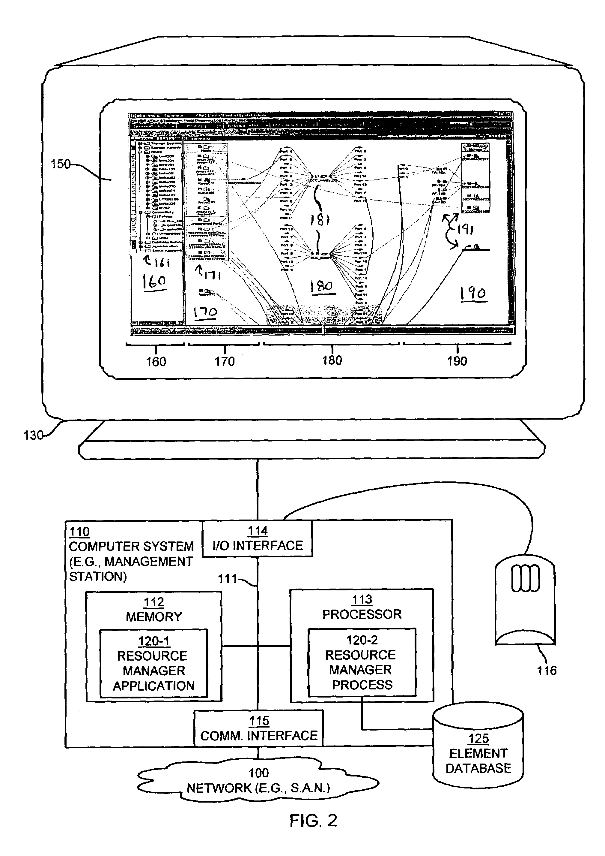
[0021]Other embodiments of the invention include a computerized device, such as a host computerized device, workstation or other computerized device configured to process all of the aforementioned method operations disclosed herein as embodiments of the invention to provide a network topology view and associated resource management operations. In such embodiments, the computerized device includes a display, a memory system, a processor and an interconnection mechanism connecting the display, the processor and the memory system. The memory system is encoded with a resource management application that when performed on the processor, produces a resource management process that includes a graphical user interface produced on the display of the computerized device. The graphical user interface allows the resource management process to perform all of the method embodiments and operations explained herein as embodiment of the invention.

Problems solved by technology

Conventional network management software applications and computerized devices that provide graphical user interfaces for management and visual representation of manageable network resources suffer from a variety of deficiencies.
In particular, conventional network management software applications do not uniformly present network topology views in a consistent and optimal manner for ease of use by a user of such software applications.
Each of these conventional techniques for displaying a network topology or interconnection of manageable network resources suffer from deficiencies due in large part to a lack of ergonomic considerations given to a user's ability to visually scan, identify, select and then apply management commands to specific manageable network resources of interest to that user within such conventional network views.
That is, conventional network topology views make it difficult for a user to identify and then select particular managed resources of interest due to the complex graphical layouts that such conventional applications provide.
This circular scanning process can become confusing and time-consuming to the user in situations in which there are many host icons present in the conventional star topology or in situations where the star topology is so large as to not be able to completely fit onto the screen or display.
This process is time consuming and cumbersome for the user.
While this conventional geographical-based network view may provide ease of device location for the network manager should he or she need to physically attend to the device, since the primary function of the network management software is to remotely manage the devices, such conventional geographical-based network topology views suffer a similar problem as the star-topology view when used for remote resource management.
This process of finding devices of interest is time-consuming for the user and can suffer from inaccuracies if a user fails to select an icon representing a device that should have been subject to the particular management operation desired by the user but that user did not see that device.
Accordingly, the deficiencies of conventional graphical displays of network topologies and layouts can result in difficulties and potentially mismanagement of the network resources.

Method used


Image

  • Methods and apparatus for managing network resources using a network topology view
  • Methods and apparatus for managing network resources using a network topology view
  • Methods and apparatus for managing network resources using a network topology view

Examples


Embodiment Construction

[0042]Embodiments of the present invention relate to mechanisms and techniques that provide a unique graphical user interface for visual representation and management of storage system resources, network resources, and / or other computer-related system or device resources that can be remotely managed. The mechanisms and techniques that provide the graphical user interface as described herein include resource management software applications and / or management computerized devices configured (e.g., programmed) to manage such resources in a storage area network. An example of a preferred embodiment is a computerized device such as a network manager's workstation that operates as a storage area network management station for management of software, computer, storage and / or other resources within a storage area network environment.

[0043]Resources that can be graphically managed by such an embodiment include both software resources such as application programs that operate on remote comput...


PUM


Abstract

Mechanisms and techniques provide a system for visualization of manageable network resources in a graphical user interface. The system displays a host element in a host display area, a storage element in a storage display area, and a connectivity element in a network display area of the network topology view on the display of the computerized device. The system displays the network display area in between the host display area and the storage display area. The system determines a coupling condition of the connectivity element in relation to at least one of the host element and the storage element and displays the coupling condition as a link on the display of the computerized device between the connectivity element and either or both of the host element and the storage element to which that coupling condition relates in order to visually convey the coupling condition to a user viewing the network topology view on the display of the computerized device.

Description

FIELD OF THE INVENTION[0001]The present invention generally relates to computer and software systems that have a graphical user interface, and more particularly, to systems and techniques that allow for management of network resources using a graphical user interface.BACKGROUND OF THE INVENTION[0002]Conventional computerized devices can operate software application programs that include a conventional graphical user interface (GUI) that allows a user of the computerized device to graphically manage, control and configure various types of hardware and software resources within computerized devices or devices coupled via a computer network. Such network management software application programs typically operate on or within a management workstation computerized device or console coupled to the computer network. The network management application renders the graphical user interface that allows, for example, a user of the management workstation to graphically select, interact with, and...

Claims


Application Information

Patent Timeline
IPC IPC(8): G06F3/00G06F17/00G06F9/00
CPCH04L41/12H04L41/22H04L41/0893
Inventor GAUVIN, FRANCOISONFFROY, JOSHUAGASSER, MORRIESHAH, KETANYEHUDA, HANNA
Owner EMC IP HLDG CO LLC
Learn More