Apparatuses for crimping and loading of intraluminal medical devices

a technology for medical devices and accessories, applied in the direction of forging/pressing/hammering equipment, prosthesis, blood vessels, etc., can solve the problems of crimping device problems, difficult calibration or external alignment efforts, balloon pinching, etc., to reduce the risk of damage to the intraluminal medical device, improve the alignment of the medical device, and reduce the risk of damage to the medical devi

Active Publication Date: 2008-01-08
BOSTON SCI SCIMED INC
View PDF41 Cites 57 Cited by
  • Summary
  • Abstract
  • Description
  • Claims
  • Application Information

AI Technical Summary

Benefits of technology

[0010]Any crimping configuration may be employed herein. Typically, such apparatuses are designed for applying relatively uniform radially inward forces to the medical device. The apparatus reduces the size of the medical device from a first diameter to a second diameter. Some such apparatuses have a plurality of coupled movable blades disposed about a reference circle to form an aperture whose size may be varied.
[0013]The plug may be of a variety of configurations. In one embodiment, the plug has conical flanges extending from the end closest the catheter delivery assembly. The conical flanges may be designed such that they more easily engage the outer catheter shaft.
[0024]The present invention, in at least some of its embodiments, therefore provides for improved alignment of the medical device with the aperture of the crimping tool thereby alleviating the need for calibration or for external alignment efforts to the aperture axis. Furthermore, at least some of the apparatuses as described herein, reduce the risk of damage to the intraluminal medical device and / or the catheter delivery assembly during transition from the crimping apparatus to the introducer apparatus.

Problems solved by technology

It can also affect the dilatation length of the stent and lead to pinching of the balloon.
Crimping and loading of self-expanding stents is often a more complicated procedure.
Alignment of the delivery system, typically the distal end of a catheter delivery device, with the crimping device can be problematic because the stent is relatively fragile, and typically the constrained outer diameter of the stent is only slightly less than the available inner diameter of the receiving delivery system or intermediate station.
If the delivery system is not properly aligned with the crimping device, the stent and / or the catheter delivery system can be damaged.
Damage may involve flaring of the ends of the catheter delivery system, or peeling or rolling of the tubing onto itself.

Method used


Image

  • Apparatuses for crimping and loading of intraluminal medical devices
  • Apparatuses for crimping and loading of intraluminal medical devices
  • Apparatuses for crimping and loading of intraluminal medical devices

Examples


Embodiment Construction

[0037]While this invention may be embodied in many different forms, there are described in detail herein specific embodiments of the invention. This description is an exemplification of the principles of the invention and is not intended to limit the invention to the particular embodiments illustrated.

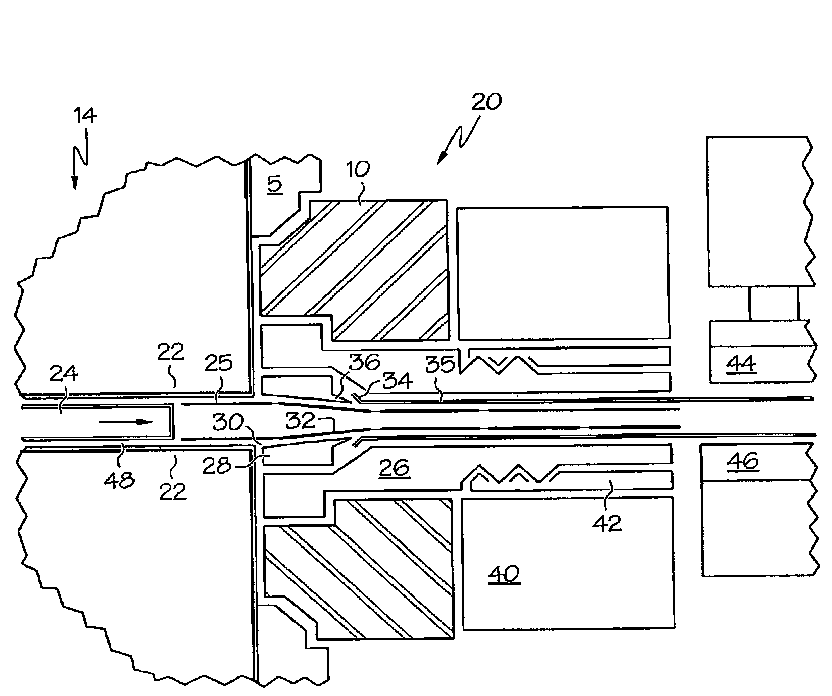
[0038]Turning now to the figures, FIG. 1 illustrates generally at 5, an internally tapered actuation hub which may be used in combination with any crimping device. As used herein, the term “crimping” shall refer to a reduction in size or profile of the medical device, i.e. the diameter of a stent, for example. The actuation hub 5 is employed for matingly engaging a loading assembly for introducing an intraluminal medical device into a catheter delivery assembly. The intraluminal device is typically introduced when its in a reduced size.

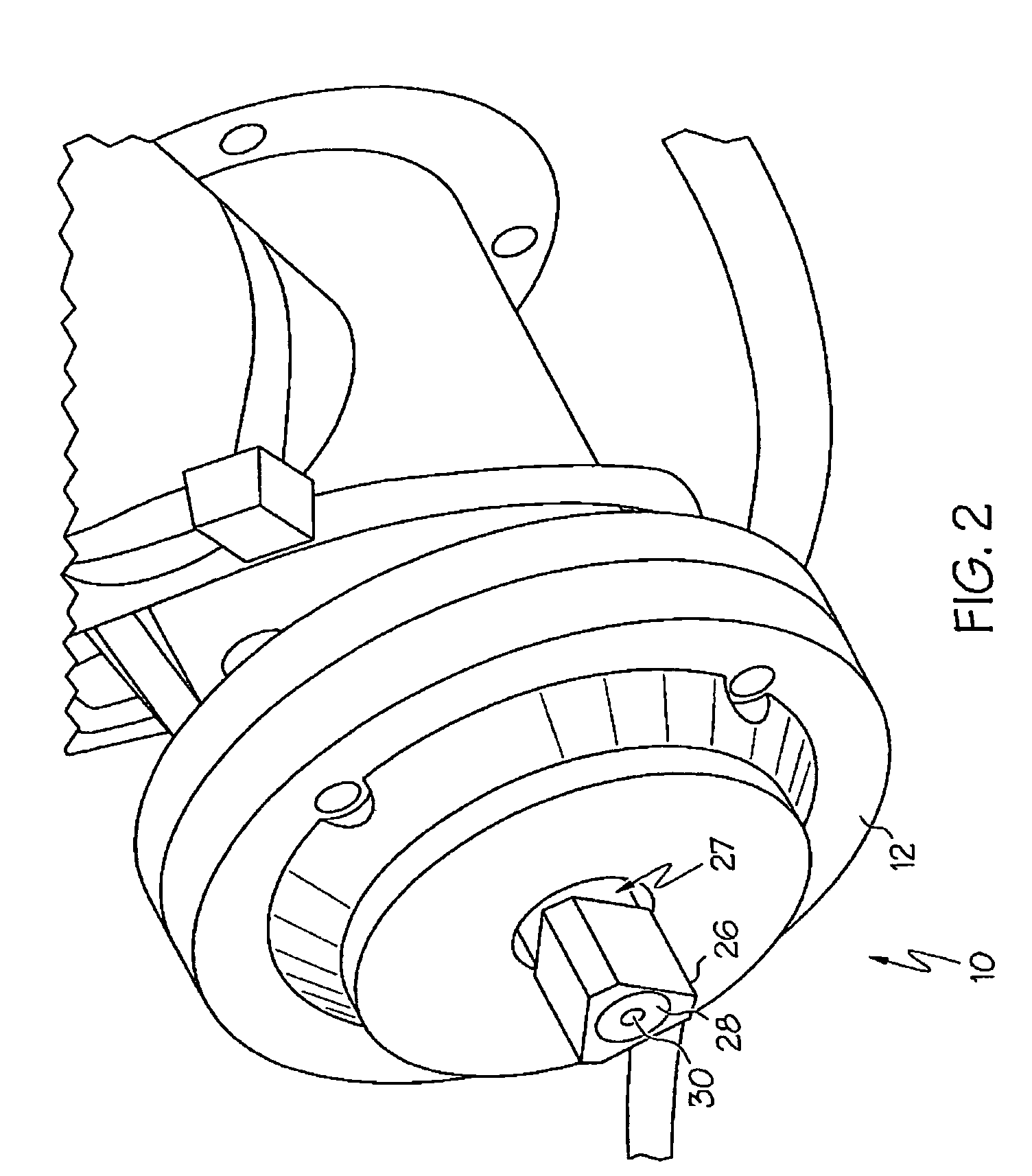
[0039]The tapered actuation hub 6 may be employed to matingly engage a counterpart plug on a stent loading assembly such as that shown generally at 10 i...


PUM

PropertyMeasurementUnit
lengthaaaaaaaaaa
lengthaaaaaaaaaa
lengthaaaaaaaaaa

Abstract

Crimping apparatuses for reducing the diameter of an intraluminal medical device from a first diameter to a second diameter prior to loading the medical device into a catheter delivery system and loading apparatuses for introducing the medical device into a catheter delivery system, the devices constructed and arranged for matingly engaging one another, combinations thereof, and methods of using the devices.

Description

BACKGROUND OF THE INVENTION[0001]This invention relates to an apparatus and methods for reducing in size an intraluminal medical device such as a stent, stent-graft, graft, or vena cava filter, and for introducing the medical device into the distal end of a delivery system for delivery of the medical device into the vasculature of a patient.[0002]Stents and stent delivery assemblies are utilized in a number of medical procedures and situations, and as such their structure and function are well known. A stent is a generally cylindrical prosthesis introduced via a catheter into a lumen of a body vessel in a configuration having a generally reduced diameter and then expanded to the diameter of the vessel. In its expanded configuration, the stent supports and reinforces the vessel walls while maintaining the vessel in an open, unobstructed condition.[0003]Stents are available in both self-expanding and inflation expandable configurations. Inflation expandable stents are well known and w...

Claims


Application Information

Patent Timeline
Patent Type & Authority Patents(United States)
IPC IPC(8): B21J7/16A61F2/06A61F2/84
CPCA61F2/95A61F2002/9522Y10T29/53387Y10T29/53996Y10T29/53065Y10T29/49913Y10T29/49908Y10T29/49927A61F2/9522A61F2/9525
Inventor PERREAULT, DANIELEDIN, MARKASMUS, BRUCE
Owner BOSTON SCI SCIMED INC
Why Eureka
Try Eureka