
Catheter with associated extension lumen

a catheter and extension lumen technology, applied in multi-lumen catheters, medical science, surgery, etc., can solve the problems of difficult challenge, limited effective aspiration catheters, and natural tendency of viscous blood to resist flow in channels

Inactive Publication Date: 2008-01-08
KENSEY NASH CORP
View PDF9 Cites 81 Cited by
  • Summary
  • Abstract
  • Description
  • Claims
  • Application Information

AI Technical Summary

Benefits of technology

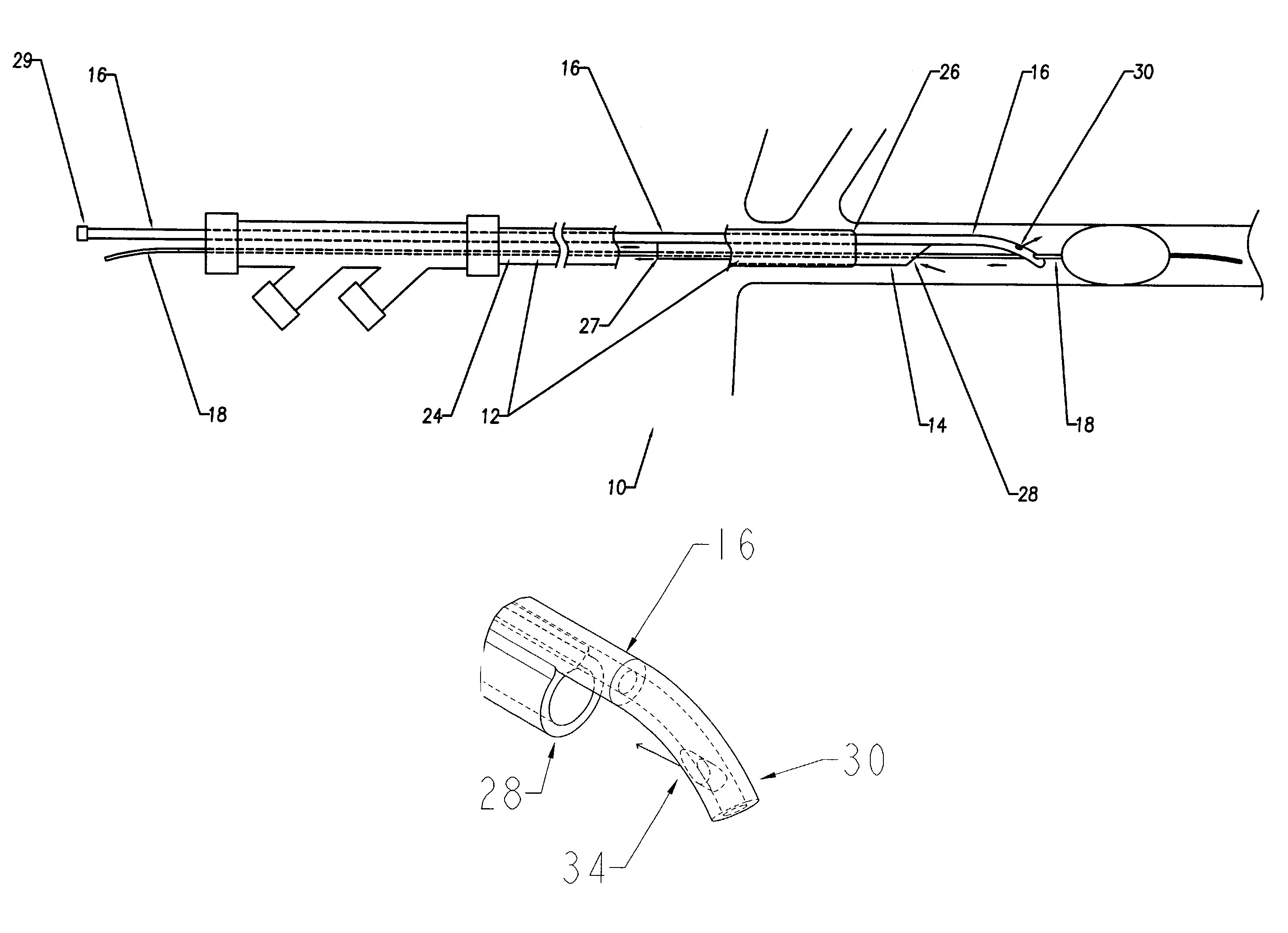
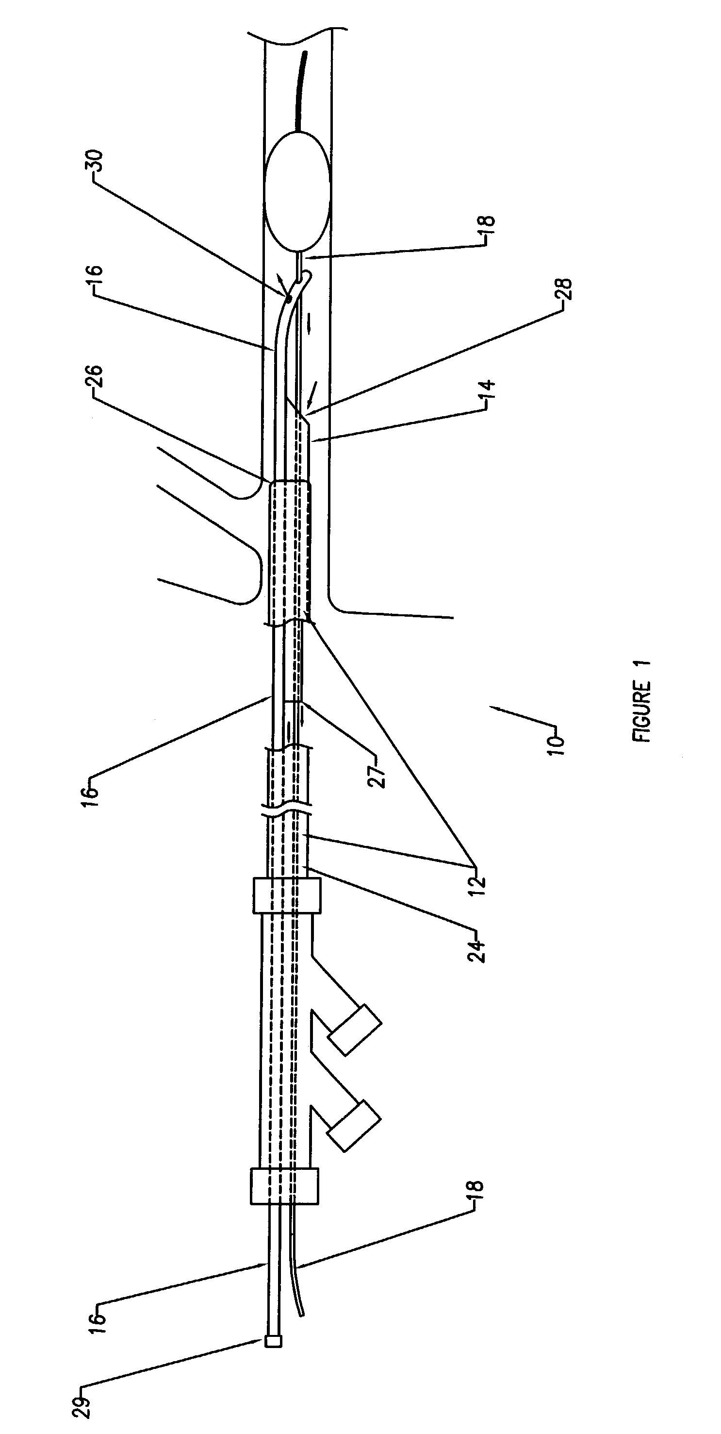
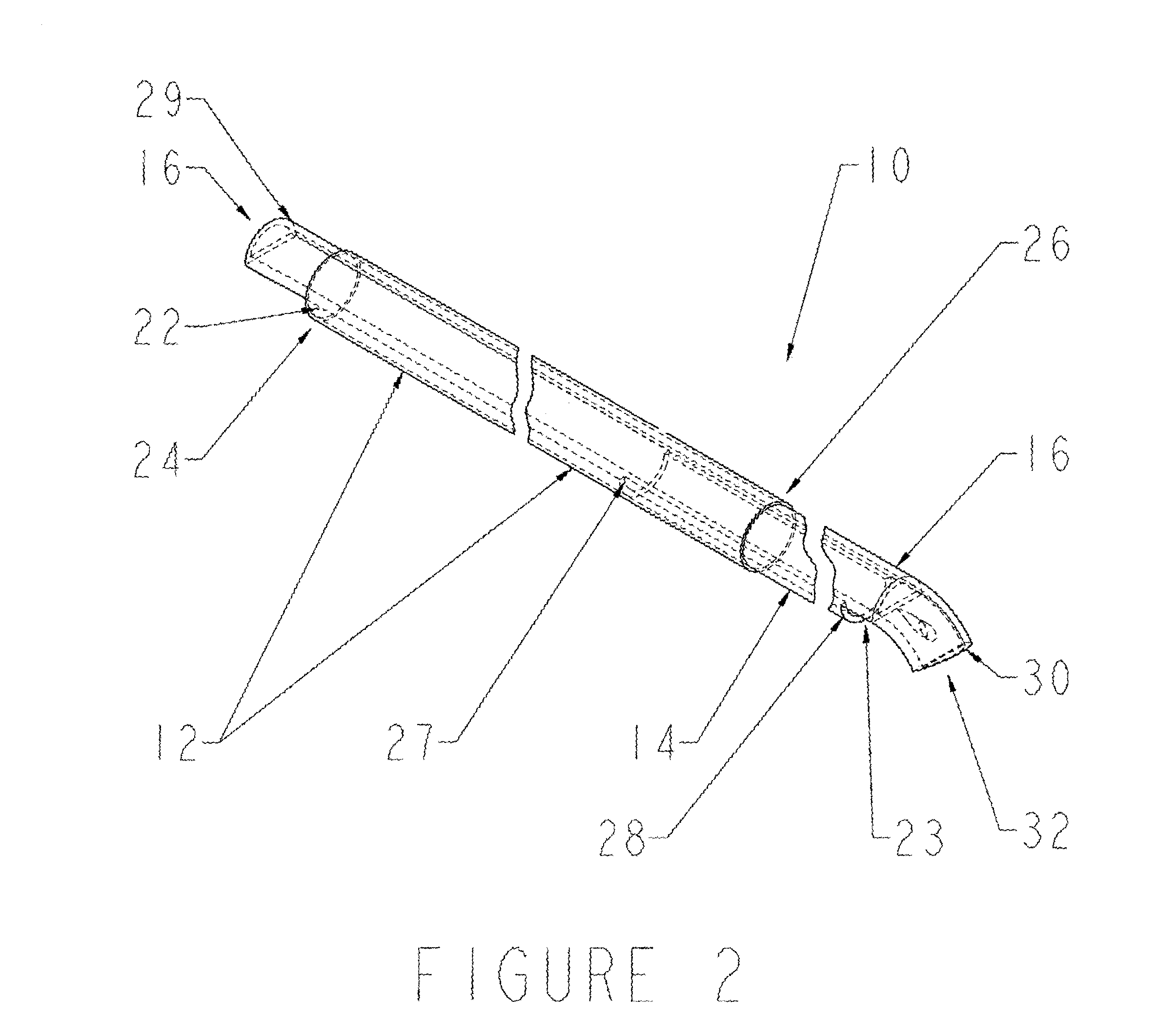
[0006]A preferred embodiment of the present invention comprises a system for accessing lumens or other vasculature in living beings for the facilitation of intraluminal or other medical procedures, with the system basically comprising a first catheter, a catheter extension, and a control / locating member. The first catheter has a proximal end and a distal end with a channel therebetween; and the catheter extension comprises a proximal end and a distal end with an extension channel therebetween. The first catheter may be arranged to slidably and telescopically accept the catheter extension in said channel with said catheter extension thereby creating an overlapping segment between the catheters. The telescoping of the catheters will cause said channel and said extension channel to operate together to form a contiguous channel.
[0008]It is anticipated that the preferred embodiment will include an extension catheter having a length that is less than that of said first catheter, although this dimension is not critical. The overlap region may affect the amount of liquid drawn in (i.e., leaked) to the channel from the lumen, during use. The degree of the fit between the outside of the extension catheter and the inside of the first catheter will also be a key factor. This design contemplates and tolerates some leakage at this overlap region; however it is also recognized that an element (e.g., a bushing, washer, or flange) may be used to decrease this effect.
[0014]The various embodiments herein comprising infusion and extraction contemplate infusion rates or volumes higher or lower than aspiration rates. It is recognized that an extraction rate higher than an infusion rate should yield in the removal of blood from the body. This may also afford some additional protection from emboli or other debris, as the removal of additional fluid should cause the clearing the procedural area and proximate areas of debris.
[0015]The introduction of infusate may be performed at high pressure which may be caused by small orifices in the extension catheter, whereby the infusate causes liquid jets to be directed from the extension catheter. These jets may be directed proximally, distally, or radially outward, or any combination thereof. Proximal jets may also assist the entry of debris into any aspiration opening in the device.

Problems solved by technology

One problem common to all aspiration catheters is the natural tendency of the viscous blood to resist flow in channels, especially when these channels are small and long as they are with typical catheters, see e.g., U.S. Pat. No. 6,152,909 (Bagaoisan et al.).
This becomes a difficult challenge when using aspiration catheters inside blood vessels since the pressure differential available to move the blood is never greater than atmospheric pressure and is often quite lower.
Given the physical constraints of this problem, effective aspiration catheters are limited to ID's approximating 1mm or larger for catheters longer than 100 cm.
Hemodialysis catheters readily overcome this problem with large ID's, however these catheters are very short, see e.g. U.S. Pat. No. 6,568,329 (Mahurkar) and U.S. Pat. No. 5,195,962 (Martin et al.).
Another problem common to blood vessel catheters is maneuverability.
In aspiration catheter constructions that involve additional functions beyond simple aspiration and thus require multiple lumens, this is especially problematic.

Method used


Image

  • Catheter with associated extension lumen
  • Catheter with associated extension lumen
  • Catheter with associated extension lumen

Examples


Embodiment Construction

[0022]It is among the objects of the present invention to facilitate intravascular or intra-luminal procedures, especially the clearing of an occluded lumen by, in various preferred embodiments, providing a device for use in delivering infusion / irrigation to the lumen, causing extraction of any debris, and providing distal protection necessary for the procedure.

[0023]Various embodiments will include, among other things, an infusate fluid pathway, and an extraction pathway, pumping means, distal protection means, guidewires, a primary or guide catheter, a catheter extension, and a locating member, various arrangements of these components are discussed below.

Extraction Pathway

[0024]The invention overcomes the drawbacks of the prior art including, but not limited to, the incorporation of measures necessary to reduce the occurrence of cavitation within the extraction pathway of the device. The invention is such that it has the ability to efficiently withdraw fluid and debris from the bo...


PUM


Abstract

An intra-luminal device for the extraction of occlusive or partially occlusive material is disclosed. Said device comprises a novel catheter extension which minimizes cavitation of extracted fluids and also allows the better navigation of tortuous lumens or vasculature.

Description

BACKGROUND OF THE INVENTION[0001]The use of aspiration catheters for a variety of medical procedures has been well established, including the use of aspiration catheters for removing blood, obstructions, thrombus, or debris from blood vessels. This can be accomplished using manual means, like a hand pump or syringe, or mechanical means such as mechanical pump. Aspiration catheters have taken the form of simple single-lumen catheters or more complicated multi-lumen catheters. Perhaps the most common aspirations performed in blood vessels are those involving aspirations of thrombus through single lumen tubes that are opened to atmospheric pressure. These aspirations are commonly performed during surgery, or done percutaneously during coronary or peripheral interventions.[0002]One problem common to all aspiration catheters is the natural tendency of the viscous blood to resist flow in channels, especially when these channels are small and long as they are with typical catheters, see e....

Claims


Application Information

Patent Timeline
Patent Type & Authority Patents(United States)
IPC IPC(8): A61M25/00A61B17/22A61M1/00
CPCA61B17/22A61B17/32037A61B2017/22039A61B2017/22082A61B2017/22084A61B2217/005A61M1/0084A61M25/0032A61M1/85A61B17/3203
Inventor NASH, JOHN E.WALTERS, GREGORY
Owner KENSEY NASH CORP
Learn More