Eureka AIR delivers breakthrough ideas for toughest innovation challenges, trusted by R&D personnel around the world.

Security and identification label and the production and use thereof

Inactive Publication Date: 2008-01-08
BIBLIOTHECA RFID LIBRARY SYST
View PDF9 Cites 0 Cited by
  • Summary
  • Abstract
  • Description
  • Claims
  • Application Information

AI Technical Summary

Benefits of technology

[0006]The invention achieves this object by providing the labels with means which reduce the influence of stray capacitances caused by the object on the resonance characteristics of the label. Surprisingly, it turns out that the disturbances caused by the objects to be identified stem, in most cases, from the occurrence of so-called capacitive couplings between the resonant circuit of the label and the object. This occurs particularly when the object has metallic elements. These capacitive couplings result in a shift of the characteristic frequency of the resonant circuit, or of the entire absorption behavior of the label, which is to say that a so-called “detuning” takes place. This detrimental shifting of the absorption behavior can be decreased or even eliminated in an astonishingly simple and efficient manner by shielding these stray capacitances of the object from the label, thus minimizing their influence.
[0007]Of course, the type, strength, and characteristics of the stray capacitances depend on the frequency used. As a rule, the higher the frequency, the more dramatic becomes the influence of stray capacitances. In view of that, it can be seen according to one of the first embodiments of the invention that the shielding of stray capacitances given an electromagnetic signal in the radio frequency range (RF signal), and particularly in the range of 10-20 MHz, can be employed especially effectively, especially with a passive label.
[0010]In another preferred embodiment of the invention, the means for the prevention or at least reduction of the capacitive coupling is formed as an additional, dielectrically active layer arranged on the side of the label facing toward the object. Particularly when, as preferred, this layer has an especially low dielectric constant ∈r, such as, for example, in the range ∈r of less than 2.5, and particularly preferred in the range ∈r of less than 2, the desired effect can be achieved with astonishing simplicity and low cost. In so doing, the layer can be, unexpectedly, a simple paper layer with a dielectric constant that is as low as possible.

Problems solved by technology

Precisely when conventional labels are affixed to such a data medium, namely, it could have been expected that the detuning would turn out to be especially strong and uncorrectable.

Method used


Image

  • Security and identification label and the production and use thereof
  • Security and identification label and the production and use thereof
  • Security and identification label and the production and use thereof

Examples


Embodiment Construction

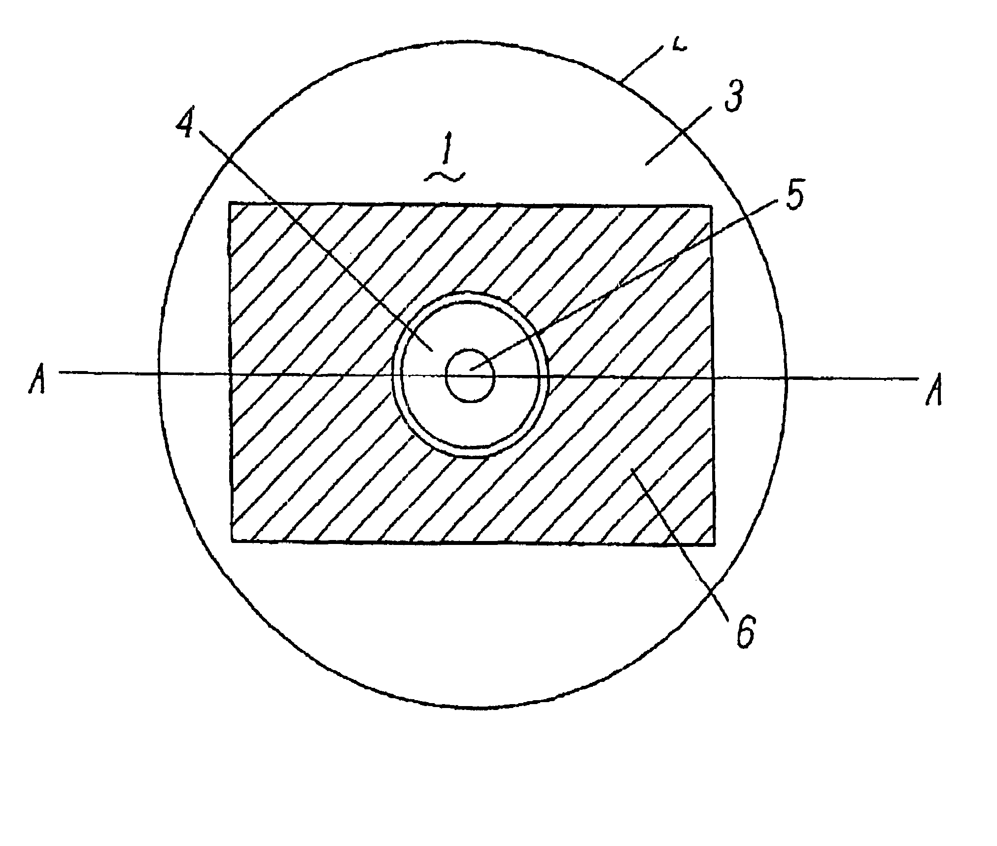
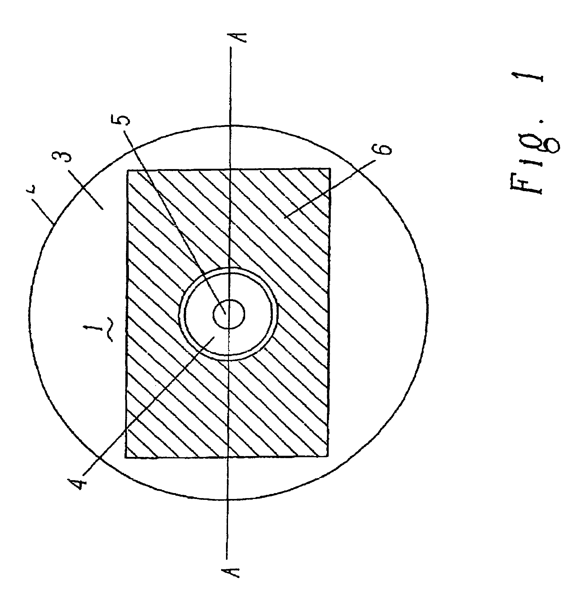
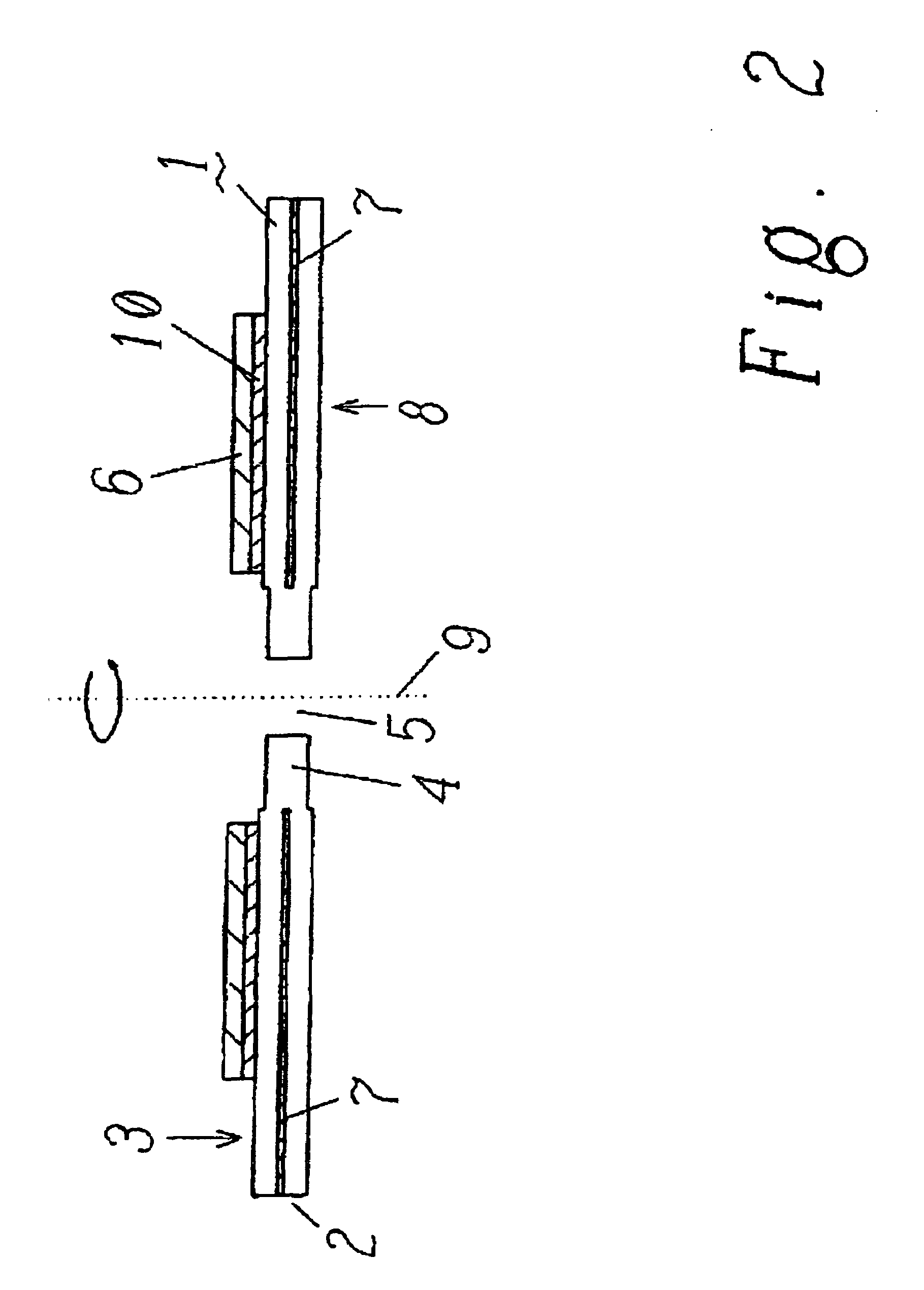
[0023]The present invention will be described by means of the example of the equipping of an existing library collection of CDs and DVDs with RFID labels.

[0024]For an automatic lending system in libraries, all materials must be provided with an RFID label so that visitors can process them at the self check-out stations. Those materials that are checked out properly may be taken out of the lending area. In order to prevent the removal of objects not checked out, a gate system is installed at the exit which reads the information in the RFID label and sounds an alarm for a non-checked-out status.

[0025]In CDs and DVDS, the problem arises that the reflective layer on the CD contains metal and impairs the function of the RFID labels. Moreover, the label should allow for reliable reading upon exit, that is to say, the transmitter(s) must also have the ability to identify the objects in a gate that is passable for the users. What's more, the label should not impair the use of the data media...


PUM


Abstract

An object is provided with a label for identifying in a cable-less manner by an electromagnetic radiation. The inventive label comprises at least one antenna receiving an incident electromagnetic signal and characterized reducing the influence of dispersion or straying capacities caused by the object on file remnant properties of the label. Such that the label can be applied to any object, particularly optical or magneto-optical data carriers.

Description

FIELD OF THE INVENTION[0001]The present invention relates to a security and / or identification label to be affixed to objects to be secured and / or identified such as, particularly, optical data media such as CDs or DVDs. Furthermore, the invention relates to the manufacture and use of such a label, as well as to an optical data medium with such a label.DESCRIPTION OF THE RELATED ART[0002]Radio frequency technology is being increasingly used for identification or anti-theft security. In the area of anti-theft security, mostly simple labels are used which are especially inexpensive to manufacture. These feature a resonant circuit which effect absorption when entering a transmittal field appropriately tuned to the characteristic frequency identification (REID) methods are used, for example, to identify objects provided with corresponding labels (so-called REID tags), as well for access control. Here there is not only a single resonant circuit located in the label, but rather the resonan...

Claims


Application Information

Patent Timeline
IPC IPC(8): G08B13/14B31D1/02G01V15/00G06K19/067G06K19/07G06K19/077G08B13/24G09F3/00G11B23/30
CPCG01V15/00G06K19/045G06K19/067G06K19/07749G08B13/2414G08B13/2417G08B13/2437G08B13/2445G11B23/40
Inventor MULLER, PHILLIP
Owner BIBLIOTHECA RFID LIBRARY SYST
Why Eureka
Eureka Blog
Learn More