Illumination apparatus and methods

a technology of illumination apparatus and illumination beam, applied in the direction of photometry using electric radiation detector, optical radiation measurement, instruments, etc., can solve the problems of reducing the sensitivity of detecting defects, degrading image quality, and ringing effect, so as to reduce the speckle noise in the incident beam and reduce the speckle noise

Active Publication Date: 2008-01-15
KLA TENCOR TECH CORP
View PDF12 Cites 21 Cited by
  • Summary
  • Abstract
  • Description
  • Claims
  • Application Information

AI Technical Summary

Benefits of technology

[0013]In a further embodiment, the illumination apparatus includes a fiber modulator for alter the length of the fibers so as to reduce speckle noise in the one or more incident beams. In a specific embodiment, the fiber modulator is a piezoelectric modulator coupled to a portion of the fibers having a voltage generator for applying a voltage difference across the piezoelectric modulator to selectively altering a size of the piezoelectric modulator and thereby stretch the coupled fibers. In a further aspect, the piezoelectric modulator is rectangular shaped and coupled to the fibers with epoxy. Alternatively, the piezoelectric modulator may have a tube shape around which the fibers are wrapped.
[0014]In an alternative embodiment, the illumination apparatus includes a rotating diffuser for receiving the incident beams and outputting the incident beams with altered phases so as to reduce speckle noise in the incident beams.
[0017]In yet another embodiment, an illumination apparatus includes a plurality of optical fibers that each has a first end and a second end and a plurality of illumination sources each adjacent to a corresponding first fiber end and being operable to transmit an incident beams onto a corresponding first fiber end so that the incident beam is output from the corresponding second fiber end. The illumination apparatus also includes a lens arrangement for receiving the incidents beams output from the second fiber ends and directing the incident beams towards the sample, wherein the lens arrangement and the fibers are arranged with respect to each other so as to image a Fourier plane of the sample at the second ends of the fibers, and a fiber modulator for altering the length of the fibers so as to substantially eliminate speckle noise in the one or more incident beams. In this embodiment, an illumination selector for transmitting incident beams onto selected fibers as described above is optional.

Problems solved by technology

One of the downsides, however, of using lasers is that the high spatial and temporal coherency of laser light can cause a ringing effect when imaging patterns on the surface of a sample, or speckle when the surface features are random.
The ringing effect or speckle can severely degrade image quality and introduce excessive noise, therefore reduce sensitivity for detecting defects.
One problem associated with using a rotating diffuser involves illumination efficiency.
Diffusers are generally low efficiency because of excessive scattering of light.
This can be a serious concern since the amount of incident light as part of the overall light budget for most laser inspection systems is limited.
This is especially true for deep UV inspection systems where the light budget is extremely restricted.

Method used


Image

  • Illumination apparatus and methods
  • Illumination apparatus and methods
  • Illumination apparatus and methods

Examples


first embodiment

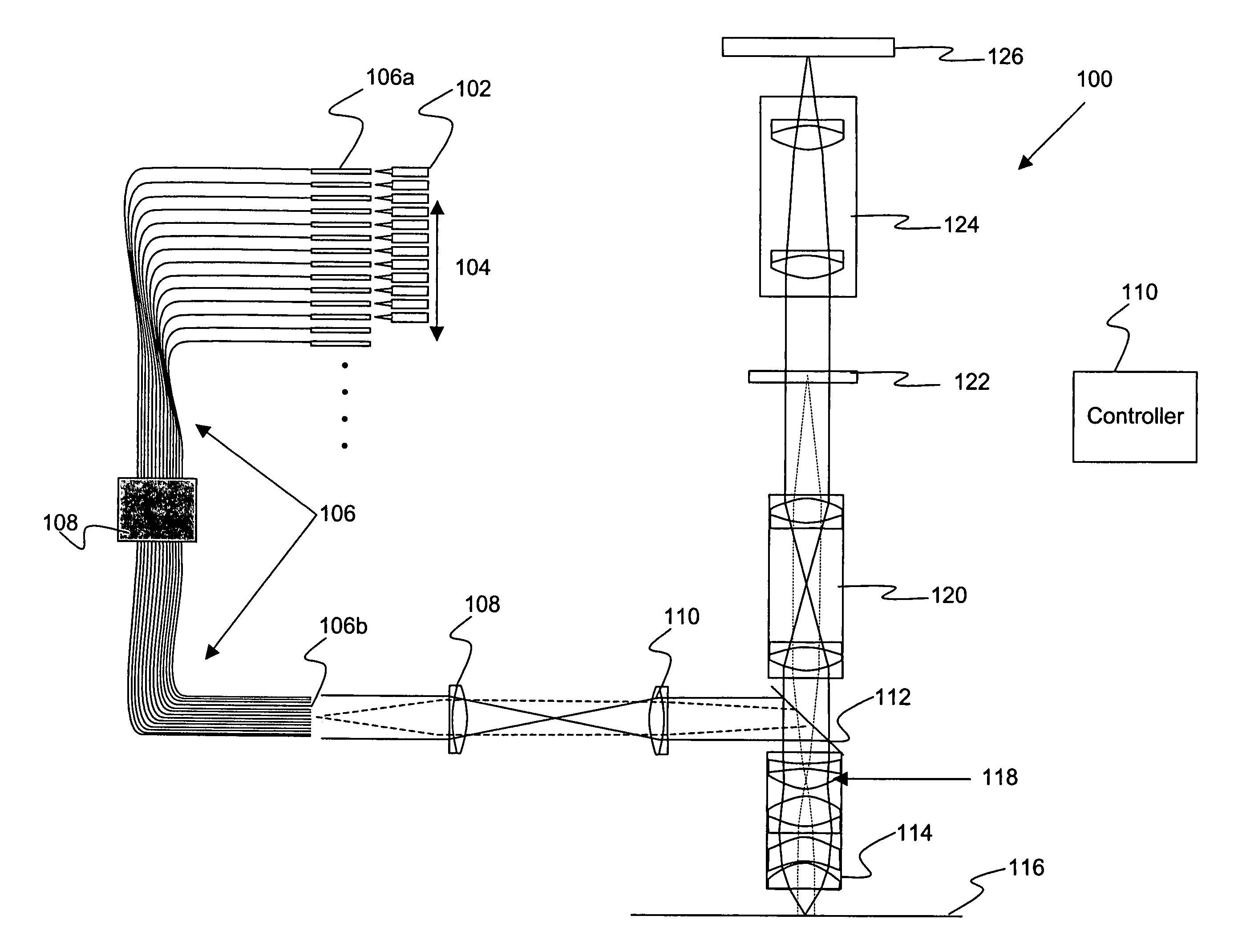
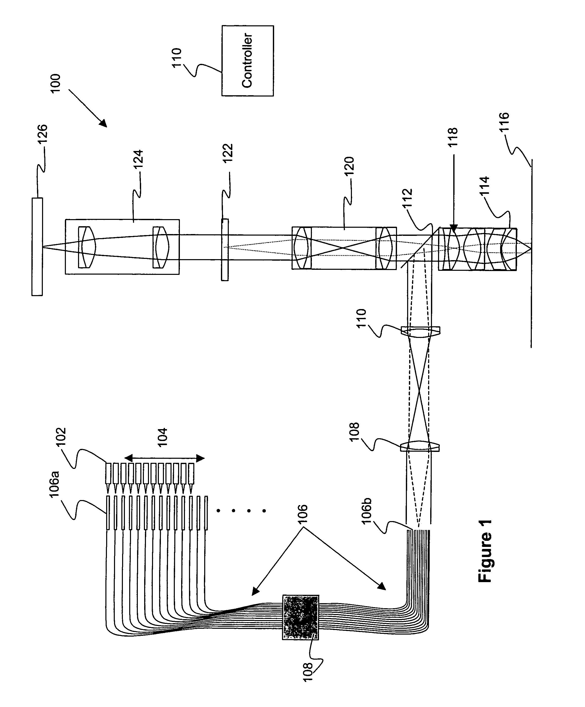
[0055]FIG. 3A illustrates an arrangement of illumination sources with respect to a group of fibers in accordance with the present invention. In the example of FIG. 3A, the first fiber ends 106a of FIG. 1 are shown. As shown, the illumination sources 1 through 13 are arranged to cover adjacent fibers 1 through 13, while fibers 14 through N are not covered by a corresponding illumination source. Although a one dimensional arrangement of illumination sources and fibers are shown, these arrangements may be two dimensional when the laser sources are not identical, for example, when the lasers have different wavelengths. In one specific example, a two dimensional arrangement may be necessary so that a lasers cannot “jump over” another adjacent laser. In the illustrated embodiment, the illumination sources may be moved to cover a different set of fibers. For example, the illumination sources 1 through 13 may be moved to cover fibers 2 through 14 or 3 through 15, etc.

second embodiment

[0056]The illumination sources may be arranged in any suitable manner with respect to the fibers. FIG. 3B illustrates an arrangement of illumination sources with respect to a group of fibers in accordance with the present invention. As shown, an illumination source is positioned adjacent to every two fibers. For example illumination source 1 is arranged over fiber 1, while illumination source 2 is arranged over fiber 3. The fiber 2 which is between fibers 1 and 3 is not adjacent to an illumination source in this configuration. These illumination sources may be moved to cover different ones of the fibers. For example illumination source 1 may be moved to cover fiber 2, while illumination source 2 is moved to cover fiber 4, etc. The different arrangements of positioning different lasers to launch light into different fibers produce desired illumination pattern of the second fiber end 106b.

[0057]The fiber modulator 108 of the inspection system 100 of FIG. 1 may take any suitable form ...


PUM


Abstract

Disclosed are apparatus and methods for illuminating a sample, e.g., during an inspection of such sample for defects. In one aspect, the illumination apparatus includes a bundle of fibers that each has a first end and a second end. The illumination apparatus further includes an illumination selector for selectively transmitting one or more incident beams into one or more corresponding first ends of the optical fibers so that the selected one or more incident beams are output from one or more corresponding second ends of the fibers. The illumination apparatus also includes a lens arrangement for receiving the selected one or more incidents beams output from the corresponding one or more second ends of the fibers and directing the selected one or more incident beams towards the sample. The lens arrangement and the fibers are arranged with respect to each other so as to image an imaging plane of the sample at the second ends of the fibers. In one aspect, the incident beams are laser beams. In a specific application of the invention, the sample is selected from a group consisting of a semiconductor device, a semiconductor wafer, and a semiconductor reticle.

Description

CROSS REFERENCE TO RELATED PATENT APPLICATION[0001]This application claims priority of U.S. Provisional Patent Application No. 60 / 533,741, entitled ILLUMINATION APPARATUS AND METHODS, filed 29 Dec. 2003 by Mehdi Vaez-Iravani, et al., which application is incorporated herein by reference in its entirety for all purposes.BACKGROUND OF THE INVENTION[0002]This invention pertains to apparatus and methods for illuminating a sample, such as a semiconductor wafer or photomask in an inspection system. It also pertains to apparatus and methods for reducing speckle effects during such illumination and inspection.[0003]A diverse number and type of inspection systems are available for inspecting samples for defects. Lasers are often used as light sources in many inspection systems to detect defects on wafers or photomasks. Lasers provide one of the most efficient illumination methods due to their extremely high brightness.[0004]One of the downsides, however, of using lasers is that the high spat...

Claims


Application Information

Patent Timeline
Patent Type & Authority Patents(United States)
IPC IPC(8): G01J1/42G02B6/32G08B5/36G02B6/00G02B6/04G02B27/48
CPCG02B27/48G02B6/0001G02B6/04
Inventor VAEZ-IRAVANI, MEHDIZHAO, GUOHENGSTOKOWSKI, STANLEY E.
Owner KLA TENCOR TECH CORP
Why Eureka
Try Eureka