Supercharge Your Innovation With Domain-Expert AI Agents!

Transmitter image suppression in TDD transceivers

a transceiver and transmitter image technology, applied in the field of communication, can solve the problems of high cost and complexity of filtering process, steep roll-off, more costly and complex, etc., and achieve the effect of minimizing the transmission of unwanted image frequency signals

Inactive Publication Date: 2008-01-15
ST ERICSSON SA
View PDF12 Cites 2 Cited by
  • Summary
  • Abstract
  • Description
  • Claims
  • Application Information

AI Technical Summary

Benefits of technology

[0011]It is an object of this invention to provide a method and apparatus that minimizes the transmission of unwanted image frequency signals from a transceiver. It is a further object of this invention to provide a method and apparatus that minimizes the transmission of unwanted image frequency signals from a transceiver that does not require the use of precision components in the transceiver. It is a further object of this invention to provide a method and apparatus that minimizes the transmission of unwanted image frequency signals from a transceiver that allows for a dynamic adjustment of the transceiver performance to compensate for component variations and environmental changes.

Problems solved by technology

As is known in the art, the cost and complexity of a filter process is highly dependent upon the degree of “roll-off” required of the filter.
The selective filtering of two signals that are close in frequency requires a very steep roll-off, and therefore is more costly and complex than the selective filter of two signals that are widely separated in frequency.
However, a high intermediate frequency introduces additional costs and complexities to the components utilized within the transmitter 130 and receiver 110 compared to a lower intermediate frequency.
The use of precision components and robust design techniques that provide for this idealized transmitter performance, however, is also a costly and complex approach.

Method used


Image

  • Transmitter image suppression in TDD transceivers
  • Transmitter image suppression in TDD transceivers
  • Transmitter image suppression in TDD transceivers

Examples


Embodiment Construction

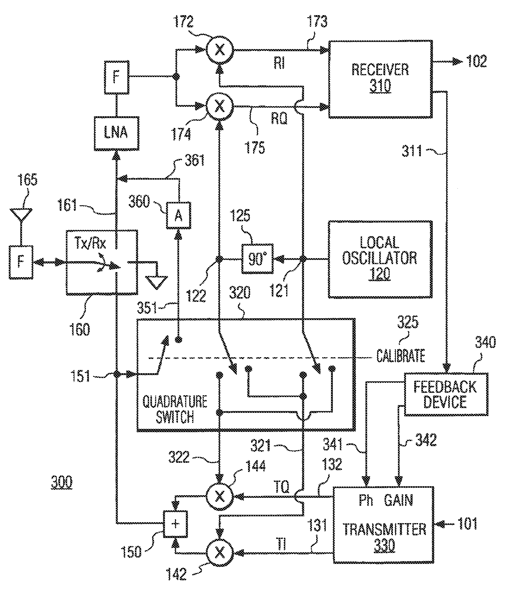
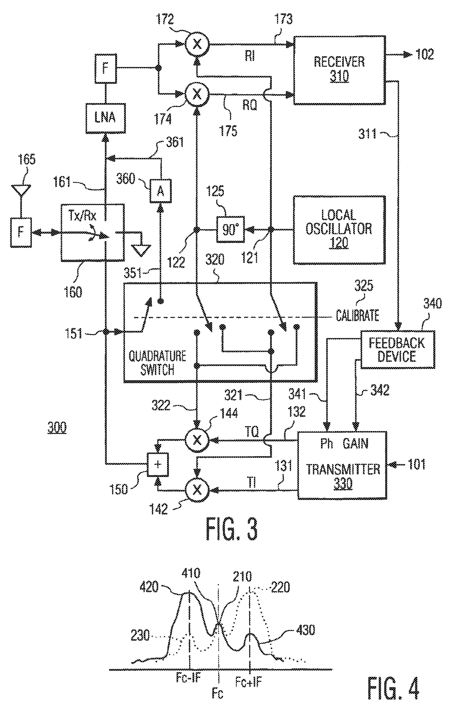
[0021]FIG. 3 illustrates an example block diagram of a time-division-duplex transceiver 300 in accordance with this invention. The transceiver 300 is configured to allow for the receiver 310 of the transceiver 300 to receive the composite transmit signal 151 from the transmitter 330 of the transceiver 300. A switch 320 effects the coupling of the composite signal 151 to the demodulators 172, 174 when a calibrate signal 325 is asserted. Also illustrated is an optional attenuation device 360 that attenuates the switched composite signal 151 to form an attenuated composite signal 361 at a signal strength corresponding to the signal strength of the typical received composite signal 161 from the antenna 165. While in the calibrate mode, the receive / transmit switch 160 decouples the received composite signal 161 from the receive signal path. The receiver 310 provides a characterization signal 311, such as a signal strength indication at one or more select frequencies, that is fed back to ...


PUM


Abstract

In a transceiver comprising a time-division-duplex (TDD) of transmit and receive functions, the characteristics of unwanted image signal energy being transmitted from the transceiver are determined, and thereafter feedback is provided to the transmitter to reduce this unwanted image signal energy. The image signal energy is measured by the receiver component of the transceiver and fed back to the transmitter component of the transceiver. The transmitter component uses the fed back information to adjust the gain and or phase relationship between the quadrature signals that are subsequently quadrature-phase modulated and transmitted. A variety of techniques can be employed to allow the image signal energy to be measured directly by the receiver component. The phase modulation signals at the transmitter can be interchanged, so that the unwanted image signal energy is transmitted in the sideband of the intended signal. Alternatively, the phase modulation signals at the receiver can be interchanged, so that the receiver's operating frequency is shifted from the frequency of the transmitter's intended signal sideband to the frequency of the transmitter's unwanted image signal sideband.

Description

CROSS REFERENCE TO RELATED APPLICATIONS [0001]This is a continuation of prior application Ser. No. 09 / 460,929 filed Dec. 14, 1999, now U.S. Pat. No. 6,717,981.BACKGROUND OF THE INVENTION[0002]1. Field of the Invention[0003]This invention relates to the field of communications, and in particular to time-division-duplex (TDD) transceivers with a common transmit and receive frequency.[0004]2. Description of Related Art[0005]Time-division-duplex (TDD) transceivers are commonly used to provide two-way communications using a single carrier signal frequency. FIG. 1 illustrates an example block diagram of a conventional time-division-duplex transceiver 100 that utilizes quadrature modulation. The transceiver 100 includes a transmitter 130 that transforms an input data signal into quadrature signals TI 131 and TQ 132. A local oscillator 120 provides an in-phase oscillation signal 121, and a phase shifter 125 provides a quadrature-phase oscillation signal 122 that is 90 degrees out of phase w...

Claims


Application Information

Patent Timeline
Patent Type & Authority Patents(United States)
IPC IPC(8): H04B1/38H04B1/44H04B7/14H04L27/20H04L27/22H04B1/54H03F1/32H04B1/04H04B1/56
CPCH04B1/0475H04B1/62
Inventor MOHINDRA, RISHI
Owner ST ERICSSON SA
Features
  • R&D
  • Intellectual Property
  • Life Sciences
  • Materials
  • Tech Scout
  • Unparalleled Data Quality
  • Higher Quality Content
  • 60% Fewer Hallucinations
Learn More