Multi-beveled point needle and syringe having a multi-beveled point needle

a multi-beveled, needle-shaped technology, applied in the field of hypoodermic syringes and needles, can solve the problems of shrinkage during molding, lack of dimensional stability and coring, and the elastomer most thermoplastic elastomer provides little if any advantage over natural or synthetic, so as to reduce the height interval, and reduce the height of the inters

Inactive Publication Date: 2008-01-22
BECTON DICKINSON & CO
View PDF40 Cites 20 Cited by
  • Summary
  • Abstract
  • Description
  • Claims
  • Application Information

AI Technical Summary

Benefits of technology

[0009]The syringe assembly of this invention utilizes an improved five-bevel needle configuration which reduces penetration force and a needle cannula shield or sheath formed of a styrene block thermoplastic elastomer which maintains the sharpness of the needle cannula during application, sterilization and removal of the shield, and may reduce the cycle time of gas sterilization. As described above, the improved five-beveled needle cannula configuration and needle shield may be utilized with any conventional injection device, including a conventional prefilled hypodermic syringe, and the improved needle shield or sheath of this invention has further advantages when the syringe assembly is gas sterilized. A conventional syringe assembly includes a generally tubular barrel, typically made of glass, but which may also be formed from various polymers, a needle cannula fixed to the tip portion of the barrel having a lumen therethrough in fluid communication with the interior of the barrel portion and syringes. Prefillable and prefilled syringes include a needle shield having an open end and a needle passage through the open end which receives the sharp distal end of the needle cannula to protect the needle cannula and prevent loss of fluid in the syringe barrel. The needle cannula is typically formed of stainless steel, such as AISI 304, and the needle cannula is generally coated with a lubricant, such as a silicone oil. U.S. Pat. No. 5,911,711 assigned to the assignee of this application discloses preferred needle lubricants. The needle shield or sheath is typically formed of a natural or synthetic rubber generally including a significant amount of a filler to improve the mechanical properties and reduce cost. More recently, with the advent of thermoplastic elastomers replacing rubber and synthetic rubber polymers in various applications, the prior art has suggested the use of thermoplastic elastomers for syringe tip shields and tip caps. However, as set forth below, most thermoplastic elastomers provide little if any advantage over natural or synthetic rubber and vulcanizate thermoplastic elastomers suffer other disadvantages, including shrinkage during molding, lack of dimensional stability and coring. There is, therefore, a need for an improved needle cannula point configuration which reduces penetration force and a needle shield which protects and maintains the sharpness of the needle cannula point.
[0010]It is believed by the inventors that a primary reason that a patient experiences pain when a needle cannula penetrates the skin or flesh of the patient, the needle point catches on the skin or flesh as the needle penetrates. One cause of a needle point catching on the skin or flesh is believed to be due to the height of the “intersect” established at the transition between differing bevels forming the needle point. It is believed that if this transition between differing bevels forming the needle point is less pronounced, the height of the intersects would be reduced. The effect of reducing the heights of the transitions would be to approximate, from a series of bevels forming the cannula needle point, a more continuous, unitary bevel face. The resulting continuing bevel point would thus require less penetration force in entering a patient's skin and flesh. By reducing penetration force, it is believed that the patient will also experience less pain.
[0011]Accordingly, one aspect of this invention relates to a multi-beveled needle point, reducing the heights of the intersects created between merging bevels that results in a more continuous bevel face. As described above, a needle cannula has a central lumen defining an axis through the needle cannula. The multi-beveled cannula needle point defines an opening to the lumen for the passage of fluids between a medical delivery device, such as a syringe, and a patient or vessel. The multi-beveled point preferably includes a primary bevel, a pair of tip bevels, and a pair of middle bevels. Each of the middle bevels are contiguous with the primary bevel, and meet a respective one of the tip bevels at an intersect. The primary bevel is formed or otherwise provided on the cannula by inclining the central axis of the needle cannula to a first planar angle respective of a reference plane.
[0012]The needle point, formed of five distinct bevels, displays reduced height intersects, resulting in a more continuous bevel face about the opening. It is believed that by providing a series of five distinct bevels, the needle point is lengthened over the needle points conventionally in use, and owing to the reduced height intervals, results in an effective outer diameter at the needle point less than the outer diameter of the needle points currently in use, all of which contribute to reduced needle penetration force.
[0013]The needle shield of this invention is formed of a styrene block thermoplastic elastomer, most preferably a styrene block(polyethylene / butylene) thermoplastic elastomer having a Shore A hardness of between 30 and 90 or more preferably between 45 and 65. The needle shield includes an open end and a passage through the open end configured to receive the needle cannula and preferably encloses the entire needle cannula and a portion of the syringe tip to fully protect the cannula and prevent entry of microorganisms following sterilization. In the most preferred embodiment, the internal passage includes an integral annular rib, adjacent the open end, which assures retention of the needle shield on the syringe tip portion and the needle shield is preferably enclosed by a rigid cover or shield.
[0016]The most preferred embodiment of the needle shield for a syringe needle cannula of this invention is formed of a styrene block poly(ethylene / butylene) thermoplastic elastomer having a Shore hardness of between 45 and 65. The most preferred composition for the needle shield of this invention also includes about one to three percent colorant which contains carbon black to improve structural integrity and reduce coring.

Problems solved by technology

However, as set forth below, most thermoplastic elastomers provide little if any advantage over natural or synthetic rubber and vulcanizate thermoplastic elastomers suffer other disadvantages, including shrinkage during molding, lack of dimensional stability and coring.

Method used


Image

  • Multi-beveled point needle and syringe having a multi-beveled point needle
  • Multi-beveled point needle and syringe having a multi-beveled point needle
  • Multi-beveled point needle and syringe having a multi-beveled point needle

Examples


Embodiment Construction

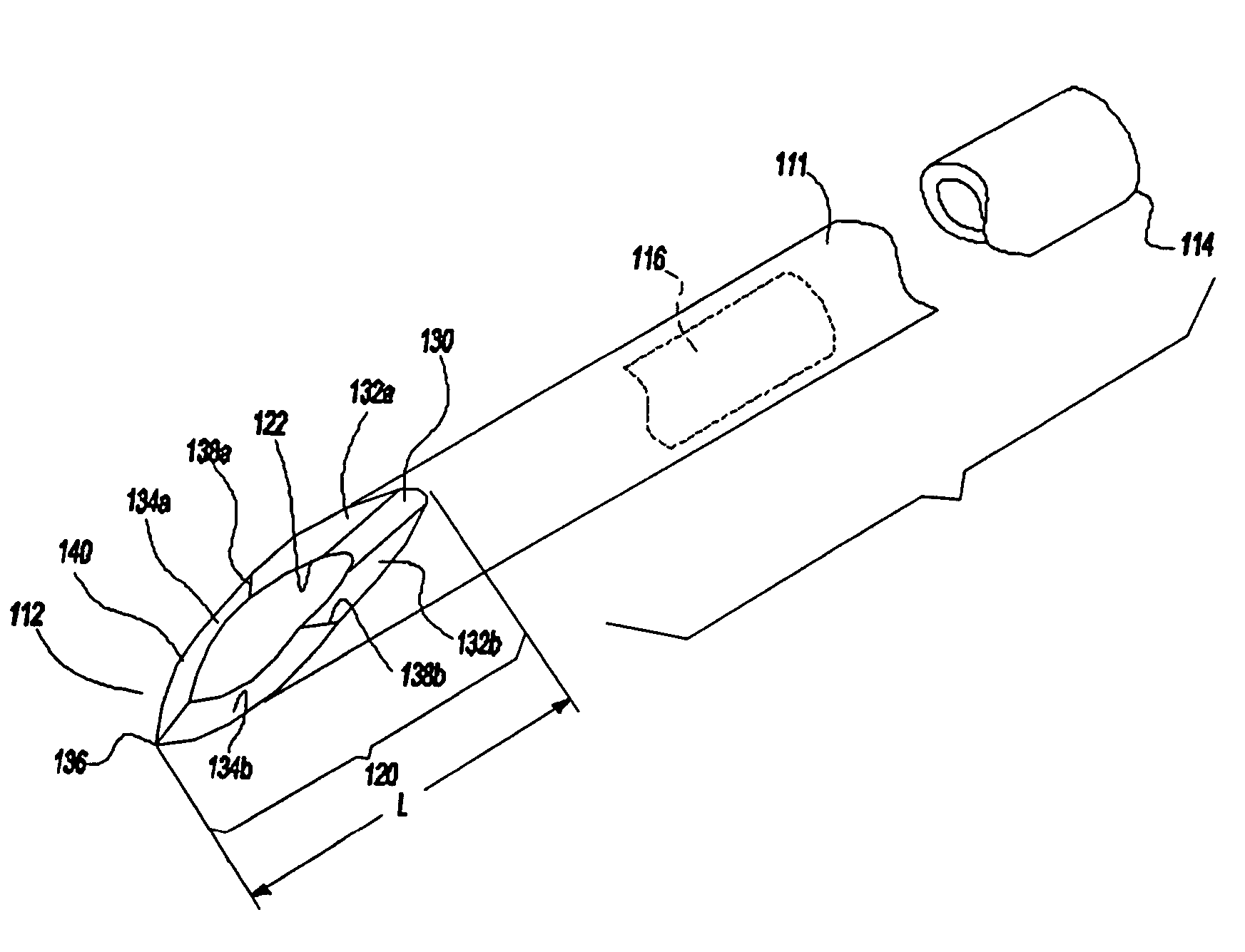
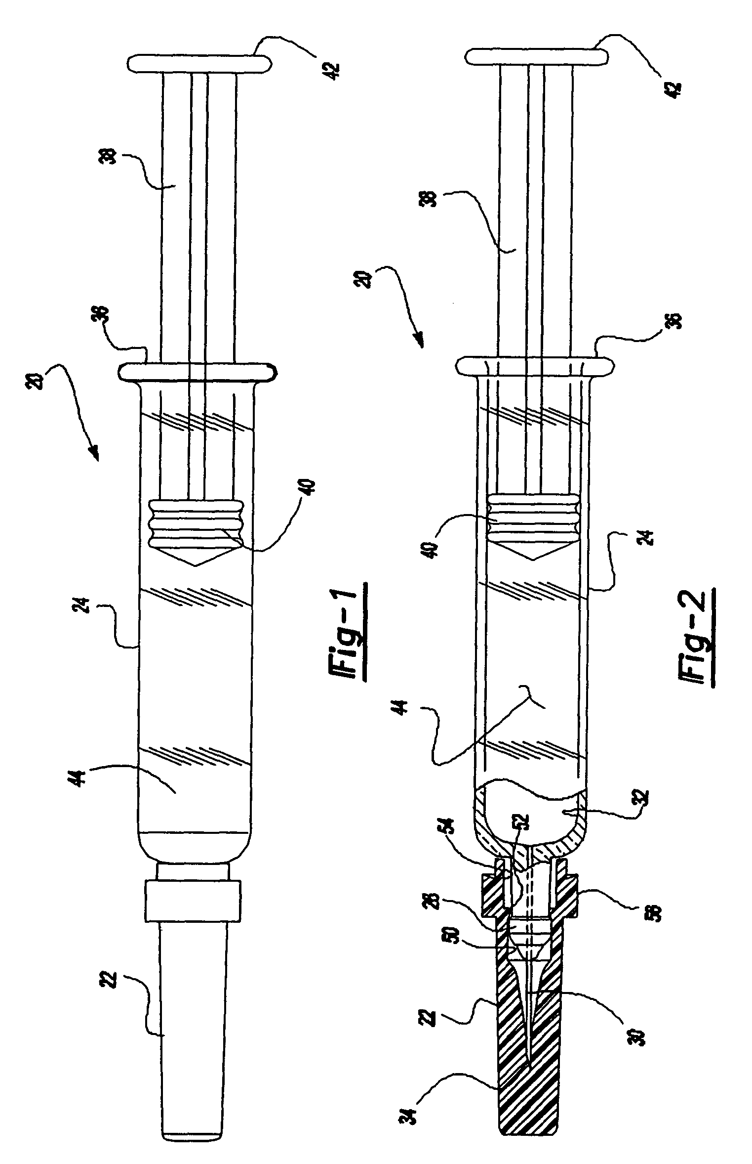
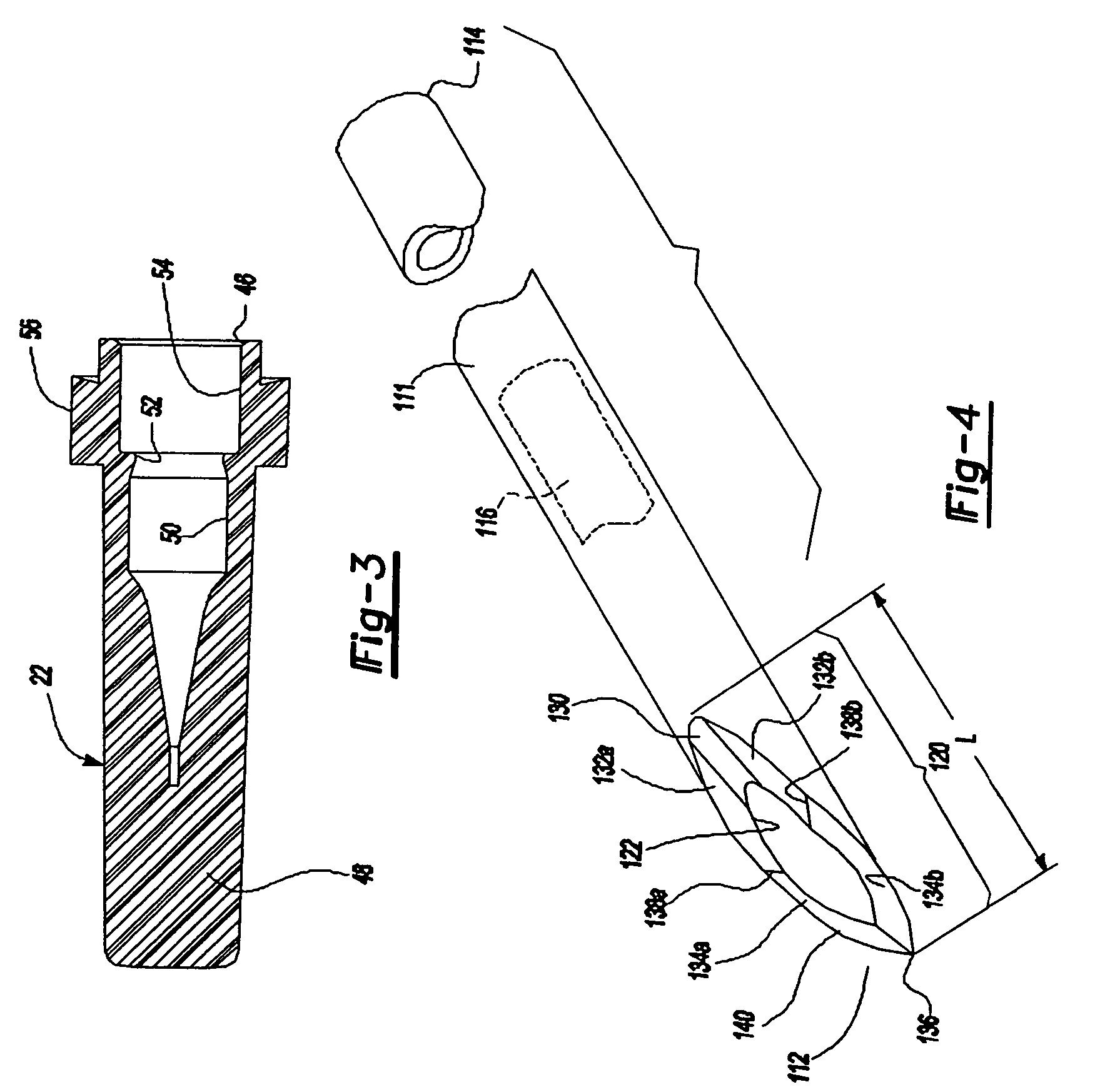
[0027]The syringe assembly 20 illustrated in FIGS. 1 and 2 and the needle shield or sheath illustrated in FIGS. 2 and 3 may be generally conventional in configuration except as described below and may take various forms within the purview of the appended claims. That is, the syringe assembly 20 may be any conventional injection device, such as the syringe assembly disclosed having a generally tubular barrel portion 24 including a reduced diameter tip portion 26 and a needle cannula 30 affixed by any suitable means to the tip portion 26 of the barrel, such that the lumen through the needle cannula is in fluid communication with the interior 32 of the barrel. The barrel 24 is typically formed of glass, but may also be formed of a suitable plastic, and the needle cannula 30 is typically formed of stainless steel. The sharp tip 34 of the needle cannula preferably includes a five-beveled point as shown in FIGS. 4-9 and described below.

[0028]The barrel 24 typically includes a radial flang...


PUM

PropertyMeasurementUnit
rotational angleaaaaaaaaaa
rotational anglesaaaaaaaaaa

Abstract

A syringe assembly including a needle cannula having a five-beveled point and a needle shield formed of a styrene block poly(ethylene / butylene) thermoplastic elastomer which significantly reduces needle penetration force and may reduce the cycle time for gas sterilization. The multi-beveled needle cannula point includes a primary bevel, a pair of tip bevels and a pair of middle bevels each intermediate the primary bevel and a respective tip bevel, wherein the angles of rotation of the primary bevel and the intermediate bevels are substantially equal resulting in reduced heights of intercepts between the bevels, therby reducing needle penetration force. The needle shield maintains the sharpness of the needle cannula during application, sterilization and removal of the shield and it is believed that the needle shield will also reduce the cycle time of gas sterilization as compared to rubber needle shields and vulcanizate thermoplastic elastomers.

Description

RELATED APPLICATIONS[0001]This application is a continuation application of Ser. No. 09 / 809,469, of Mar. 15, 2001, now U.S. Pat. No. 6,629,963 which application is a continuation in part application of Ser. No. 09 / 454,993, of Dec. 6, 1999, now abandoned which application was a continuation of Ser. No. 09 / 040,067, filed Mar. 17, 1998, now U.S. Pat. No. 6,009,933, which application was a divisional application of Ser. No. 08 / 670,255, filed Jun. 20, 1996, now U.S. Pat. No. 5,752,942.FIELD OF THE INVENTION[0002]The present invention relates to hypodermic syringes and needles.BACKGROUND OF THE INVENTION[0003]A hypodermic syringe typically includes a generally tubular barrel portion, which may be formed of glass or plastic, a plunger having a stopper typically formed of an elastomeric material, such as rubber or synthetic rubber, and a needle cannula typically formed from an elongated tube having a fluid-conducting lumen. Such syringes may be prefilled with a medicament, drug or vaccine w...

Claims


Application Information

Patent Timeline
Patent Type & Authority Patents(United States)
IPC IPC(8): A61M5/32A61L2/20A61M5/158B24B19/16
CPCA61M5/3202A61M5/3286B24B19/16A61M2005/3109A61M2205/195
Inventor PRAIS, A. WESLEYDOYLE, JUDITH L.KOZIOL, STEVEN L.PEROT, FREDERIC
Owner BECTON DICKINSON & CO
Why Eureka
Try Eureka