Integral air preheater and start-up heating means for solid oxide fuel cell power generators

a fuel cell power generator and air preheater technology, applied in the direction of electrochemical generators, cell components, cell component details, etc., can solve the problems of high operating temperature of air delivery components, difficult fabrication, and high material cost, and achieve substantial equipment and ducting savings, simplifying the design of the generator

Inactive Publication Date: 2008-01-22
SIEMENS AG
View PDF10 Cites 15 Cited by
  • Summary
  • Abstract
  • Description
  • Claims
  • Application Information

AI Technical Summary

Benefits of technology

[0012]The above needs are met and problems solved by providing a high temperature solid oxide electrolyte fuel cell generator comprising: a housing containing a top air feed plenum, a bottom fuel inlet, a reaction chamber containing fuel cells, and a reacted fuel-reacted air combustion chamber above the reaction chamber; wherein inlet air can be heated internally within the housing in at least one interior heat transfer zone located between reacted fuel-reacted air combustion chamber and the air feed plenum. These internal heat transfer zones / blocks / sections, generally made of a ceramic can eliminate exterior heat exchanger exterior recuperation air heaters and expensive high temperature resistant metal conduits.
[0015]The invention also resides in a method of operating a high temperature solid oxide electrolyte fuel cell generator which reacts feed fuel and feed oxidant at interior fuel cell surfaces comprising: (1) feeding oxidant into at least one interior heat transfer zone within the fuel cell generator through an oxidant feed tube; (2) contacting the oxidant feed tube within the at least one interior heat transfer zone with exhaust spent fuel and spent oxidant products; and then (3) exhausting cooled exhaust from the fuel cell generator. Here, the oxidant is not heated before entry into the fuel cell generator, resulting in substantial equipment and ducting savings and dramatically simplifying the design of the generator.

Problems solved by technology

These materials are extremely expensive and in some cases they are difficult to fabricate.
Another difficulty with present practice is that the high operating temperature of the air delivery components precludes the creation of very effective seals such as might be feasible if the use of elastomers were possible.
This situation is wasteful of energy.

Method used


Image

  • Integral air preheater and start-up heating means for solid oxide fuel cell power generators
  • Integral air preheater and start-up heating means for solid oxide fuel cell power generators
  • Integral air preheater and start-up heating means for solid oxide fuel cell power generators

Examples


Embodiment Construction

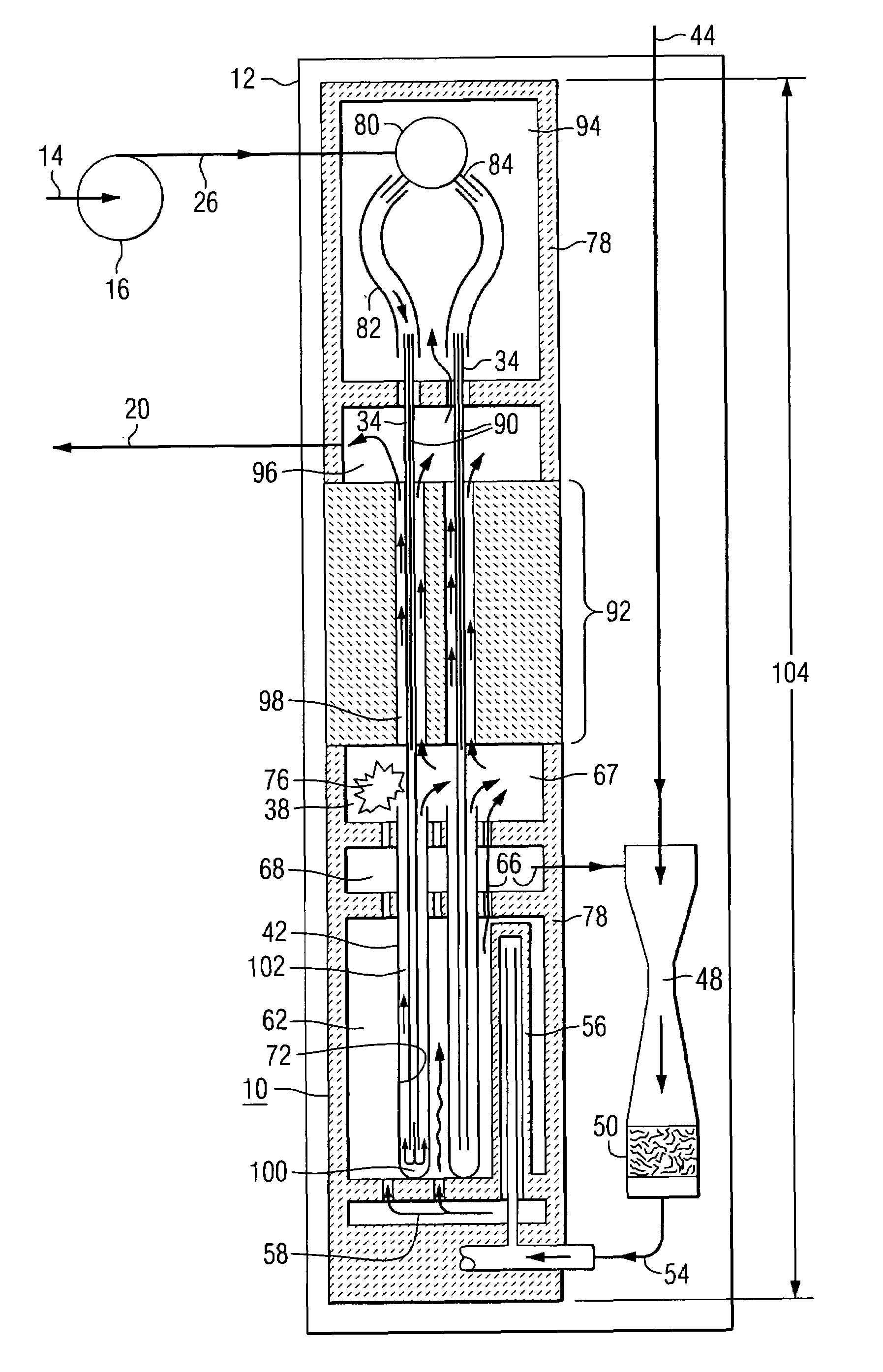
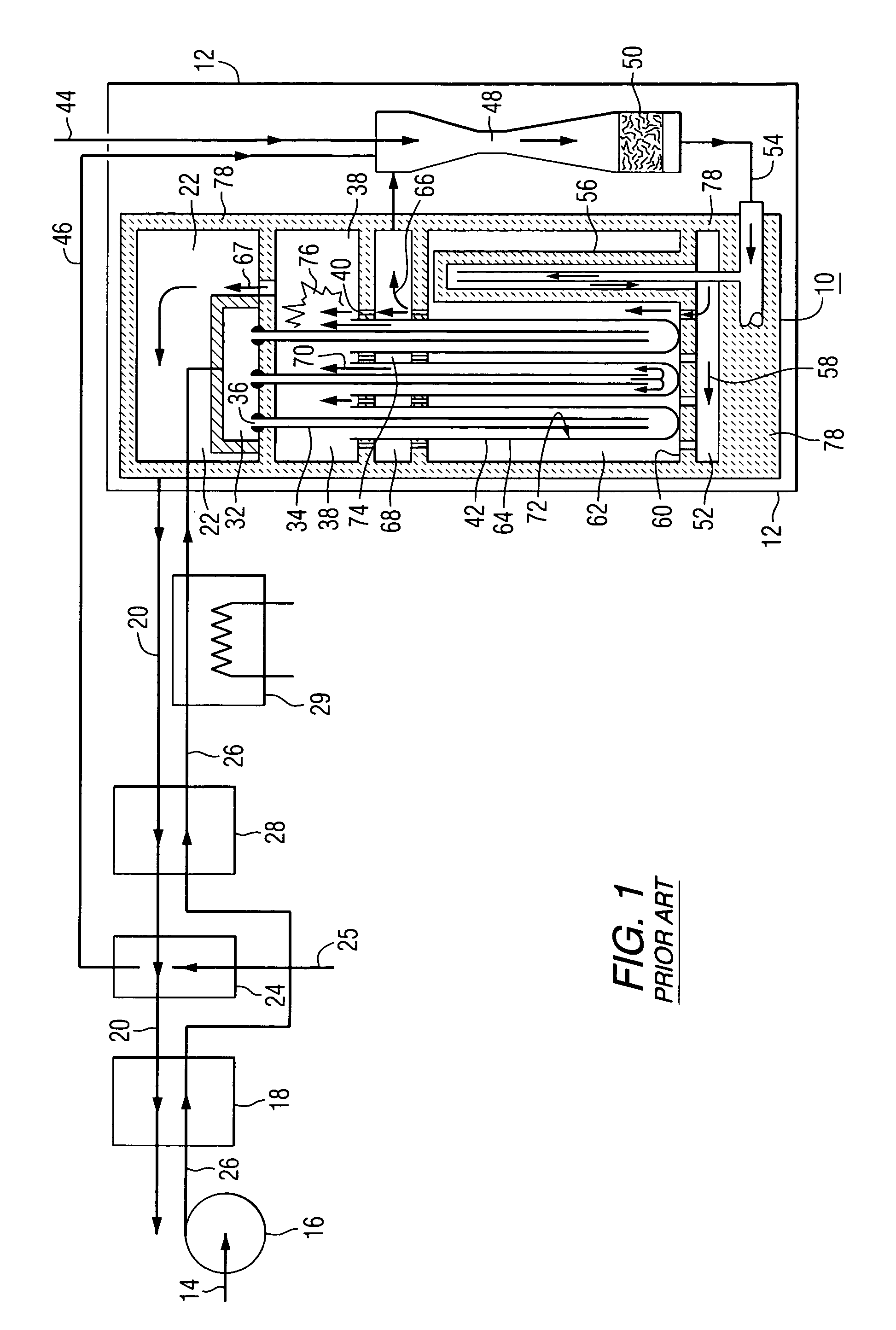
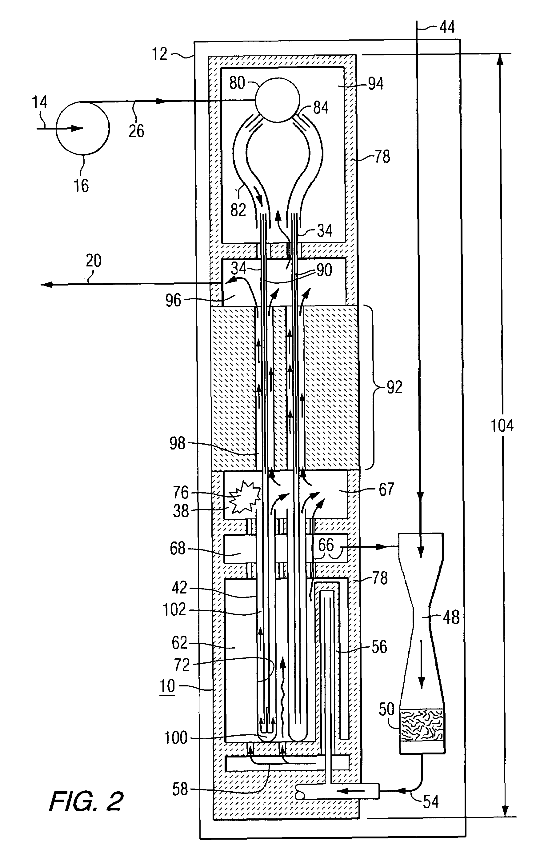
[0024]The fuel cells used inside the generator apparatus of this invention can be solid oxide electrolyte of any type or configuration. However, for purposes of simplicity, tubular, solid oxide electrolyte fuel cells will be discussed as an exemplary type useful in this invention, and the description herein-after will generally relate to that type, which shall in no way be considered limiting as to the scope of the invention.

[0025]Solid oxide electrolyte fuel cells (“SOFC”) are highly efficient devices that convert chemical energy into electricity. They operate at atmospheric or elevated pressures at a temperature of approximately 1000° C. to produce electricity using a variety of fossil fuels such as coal derived fuel gas, natural gas, or distillate fuel. The temperature of the exhaust gases from the cells is between 500° C. to 850° C., a temperature which is attractive for cogeneration applications or for use in bottoming cycles for all-electric central station power plants.

[0026]...


PUM

PropertyMeasurementUnit
temperatureaaaaaaaaaa

Abstract

A high temperature fuel cell generator (10) having a housing (12) containing a top air feed plenum (80), a bottom fuel inlet (54), a fuel reaction generator chamber (62) containing fuel cells (42) and a reacted fuel-reacted air combustion chamber (38) above the fuel reaction generator chamber (62), where inlet air (14) can be heated internally within the housing in at least one interior heat transfer zone / block (92) located between the reacted fuel-reacted air combustion chamber (38) and the air feed plenum (80).

Description

BACKGROUND OF THE INVENTION[0001]1. Field of the Invention[0002]This invention relates to preheating oxidant for a fuel cell power generator within the generator itself, simplifying the generator design and reducing costs by eliminating expensive high temperature metal manifolding and improving start-up methodology.[0003]2. Description of the Prior Art[0004]Fuel cell based, electrical generator apparatus utilizing solid oxide electrolyte fuel cells (“SOFC”) arranged within a housing and surrounded by insulation are well known, and taught, for example, by U.S. Pat. No. 4,395,468 (Isenberg) and “Solid Oxide Fuel Cell”, Westinghouse Electric Corporation, October 1992, for tubular SOFC. The tubular type fuel cells can comprise closed ended, axially elongated ceramic tube air electrode material, completely covered by thin film, ceramic, solid electrolyte material. The electrolyte layer is covered by cermet fuel electrode material, except for a thin, axially elongated, interconnection mat...

Claims


Application Information

Patent Timeline
Patent Type & Authority Patents(United States)
IPC IPC(8): H01M8/00H01M2/00H01M2/14H01M8/04H01M8/10H01M8/02H01M8/06H01M8/12H01M8/24
CPCH01M8/04022H01M8/04052H01M8/04074H01M8/04097H01M8/04201H01M8/04268H01M8/0625H01M8/243H01M8/2475H01M2008/1293Y02E60/50Y02E60/525H01M8/2485H01M8/2484
Inventor DRAPER, ROBERTJASZCAR, MICHAEL P.ZAFRED, PAOLO R.GILLETT, JAMES E.RIGGLE, MATTHEW
Owner SIEMENS AG
Why Eureka
Try Eureka