Baseband time-domain communications system

a communication system and time-domain technology, applied in the field of baseband time-domain measurement methods of communications signals, can solve the problems of inability to accurately model the inability to capture the nonlinear dynamic response of the amplifier to input signals having non-negligible bandwidth, and the inability to accurately measure the waveform accuracy of the measured waveform, etc., to reduce imbalance errors, minimize ina

Active Publication Date: 2008-01-22
THE AEROSPACE CORPORATION
View PDF2 Cites 9 Cited by
  • Summary
  • Abstract
  • Description
  • Claims
  • Application Information

AI Technical Summary

Benefits of technology

[0013]Yet another object of the invention is to provide a system for determining lowpass equivalencies of received signals by removing downconverter imbalances.
[0014]Still another object of the invention is to provide a system for providing baseband lowpass equivalencies of received signal by removing downconverter imbalances using selected phase shift of a demodulating carrier signal.
[0015]A further object of the invention is to provide a system for providing baseband lowpass equivalencies of received signal by removing downconverter imbalances using selected phase shift of a demodulating carrier signal using 0 and π / 2 phase shifts for providing a first baseband lowpass equivalence of received I and Q complex signals and using θ and θ+π / 2 phase shifts for providing a second baseband lowpass equivalence of the received I and Q complex signals.
[0016]Yet a further object of the invention is to provide a system for providing baseband lowpass equivalencies of received signal by removing downconverter imbalances using selected phase shift of a demodulating carrier signal using 0 and π / 2 phase shifts for providing a first baseband lowpass equivalence of received I and Q complex signals and using θ and θ+π / 2 phase shifts for providing a second baseband lowpass equivalence of the received I and Q complex signals with θ=π / 4+mπ / 2 where m is an integer.
[0017]The present invention is directed towards a system for minimizing inaccuracies in time-domain measurements of microwave communications signals and for removing the effects of downconverter imbalances in communication receivers. The signal measurements are accomplished by converting the signal to baseband where accurate instrumentation is available. The baseband signal is a complex signal composed of I and Q components. The I and Q waveform measurements differ by π / 2 phase shifts of a carrier signal provided by a local oscillator (LO) or carrier tracking loop used in the downconversion. Any I and Q imbalances may be detected and reduced by requiring the complex baseband signal to be invariant and apart from a rotation in the complex plane that corresponds to a change in the local oscillator phase. The complex baseband signal is measured or sampled twice, where the LO phase shift is 0, and π / 2 for the first signal measurement or sampling, and θ, and θ+π / 2 for the second. Any I and Q imbalances and baseband nonlinearities are indicated by differences between the two measured or sampled signals. The LO phase shift of θ=π / 4+mπ / 2, where m is an integer, is optimum for error detection and imbalance correction of the generated lowpass equivalencies of the measured or sampled signal. The imbalance errors may be reduced by averaging the measurements and by optimization of the measurement system. Errors caused by I and Q imbalances have been reduced to an error-to-signal power ratio of less than −56 dB. This accuracy is sufficient for communications system modeling applications.
[0018]For waveform measurements, the invention reduces I and Q imbalances as a function of frequency because the same downconverting receiver is used for both waveforms. However, an overall phase imbalance may be caused by errors in the phase shifts. Similarly, an overall amplitude imbalance may be caused by LO power level changes between the measurement of the I and Q components. Measurement errors or imbalances caused by I and Q imbalances and baseband nonlinearities are quantifiable and hence, can be removed. The communication system can be adapted to minimize imbalance errors to enhance the usefulness of baseband waveform measurements and receivers. These and other advantages will become more apparent from the following detailed description of the preferred embodiment.

Problems solved by technology

Nonlinear electronic devices are the most difficult elements to model accurately in communications simulations.
In contrast, single-tone measurements cannot capture the nonlinear dynamic response of the amplifier to input signals having non-negligible bandwidth.
The accuracy of the measured waveform is limited by distortions introduced by the waveform measurement process.
The accuracy of these instruments for measuring high-frequency signals is limited by linear amplitude and phase distortion.
The LSNA calibration eliminates any inaccuracy associated with the gain and phase response of the sampling oscilloscope, however, the LSNA still has limitations imposed by a limited number of samples and phase noise errors.
The LSNA is an advanced and expensive system, however, and requires a specialized calibration procedure.
Additionally, the LSNA can only be used to characterize arbitrary waveforms of a limited bandwidth.
This technique also yields the time-domain baseband waveform, but is corrupted by the linear filter distortions, and nonlinear baseband distortion, nonlinear RF distortions, and the I and Q imbalance between the I and Q signals in the downconverter.
The unknown distortions can be large enough to severely limit the utility of the waveform data for a precision application such as communications system modeling.
Such a system produces imbalances of the I and Q signals upon carrier demodulation.
However, the method does not remove all I and Q imbalances that lead to distortion of the input signal during downconversion.

Method used


Image

  • Baseband time-domain communications system
  • Baseband time-domain communications system
  • Baseband time-domain communications system

Examples


Embodiment Construction

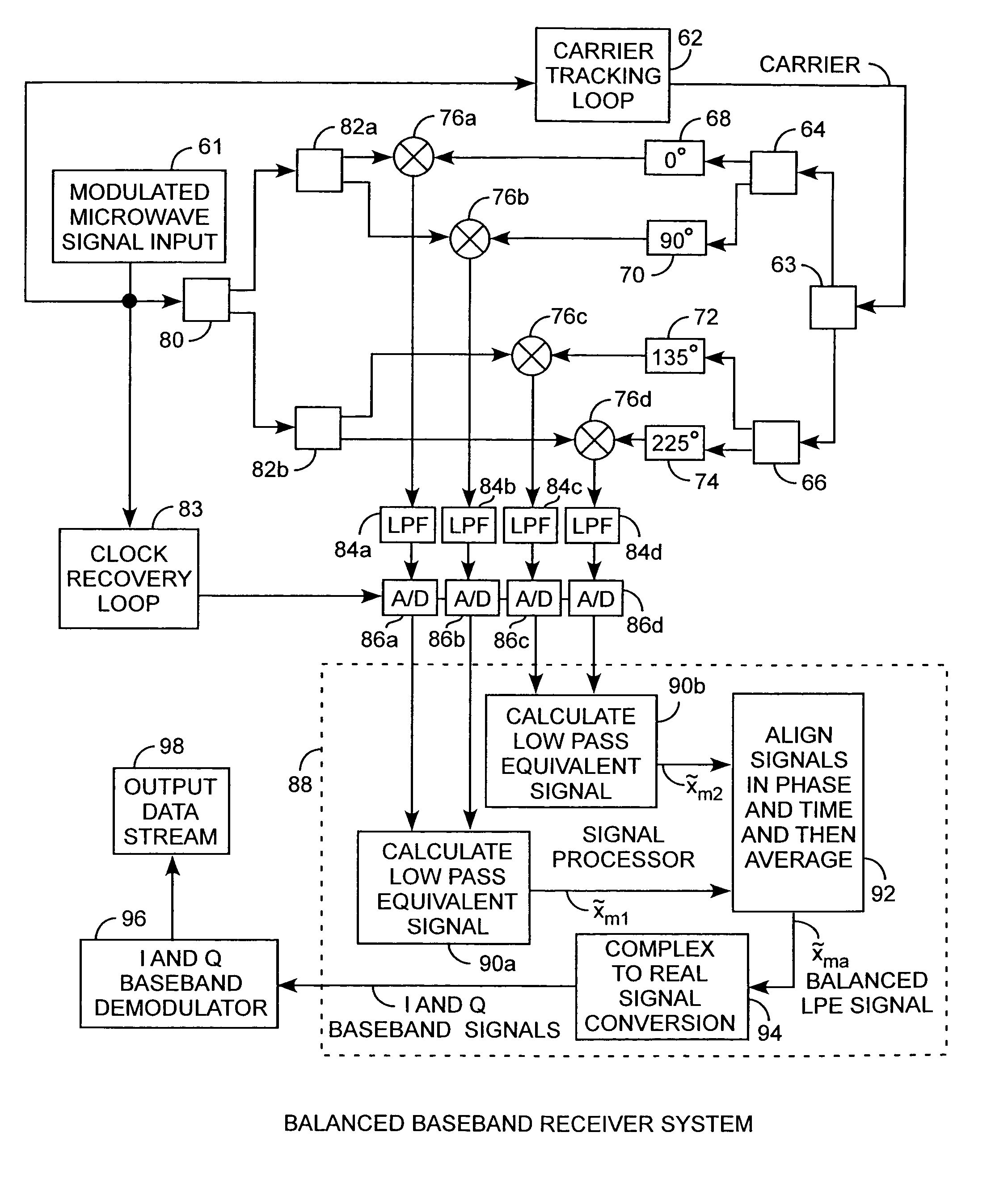
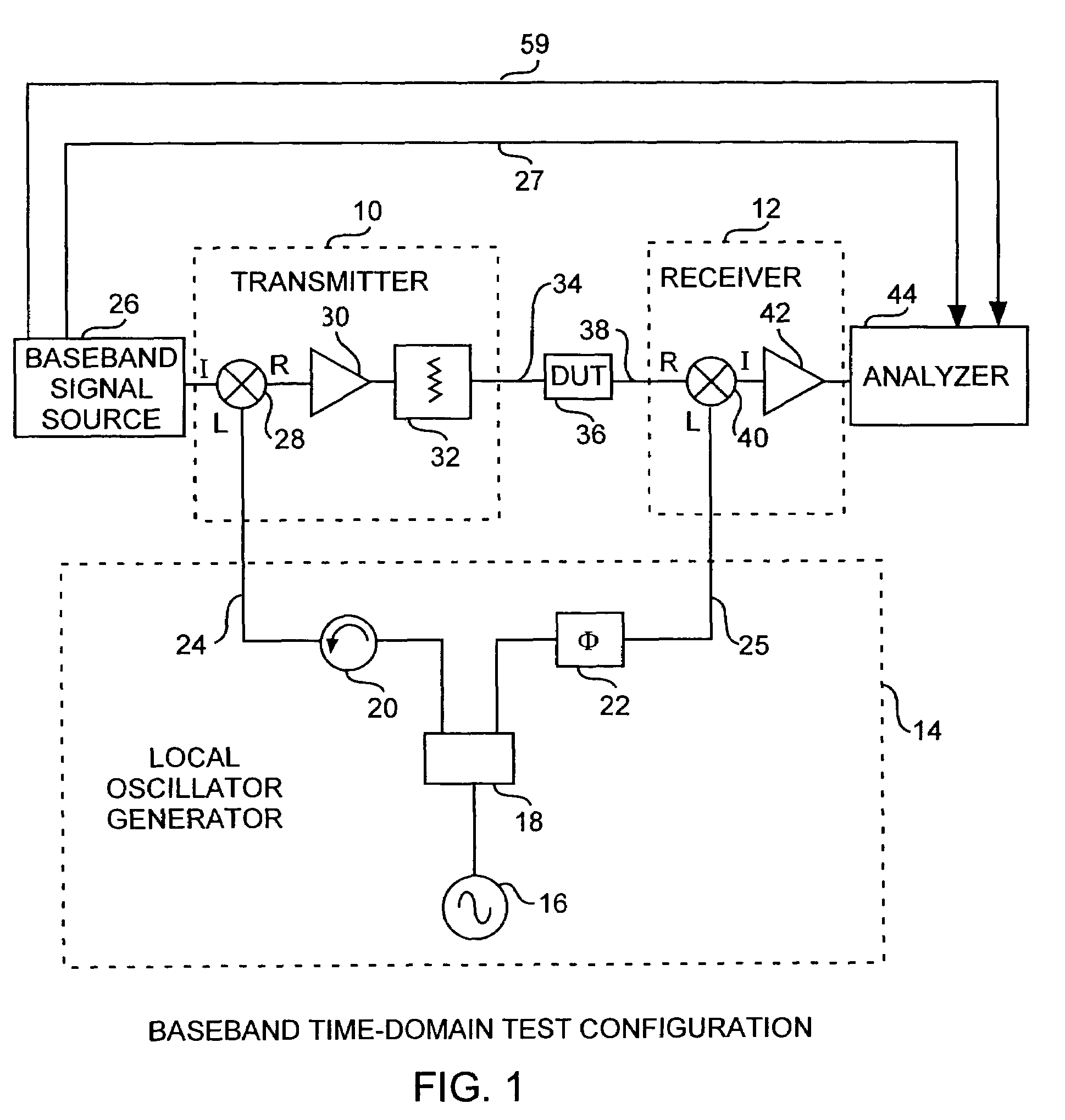
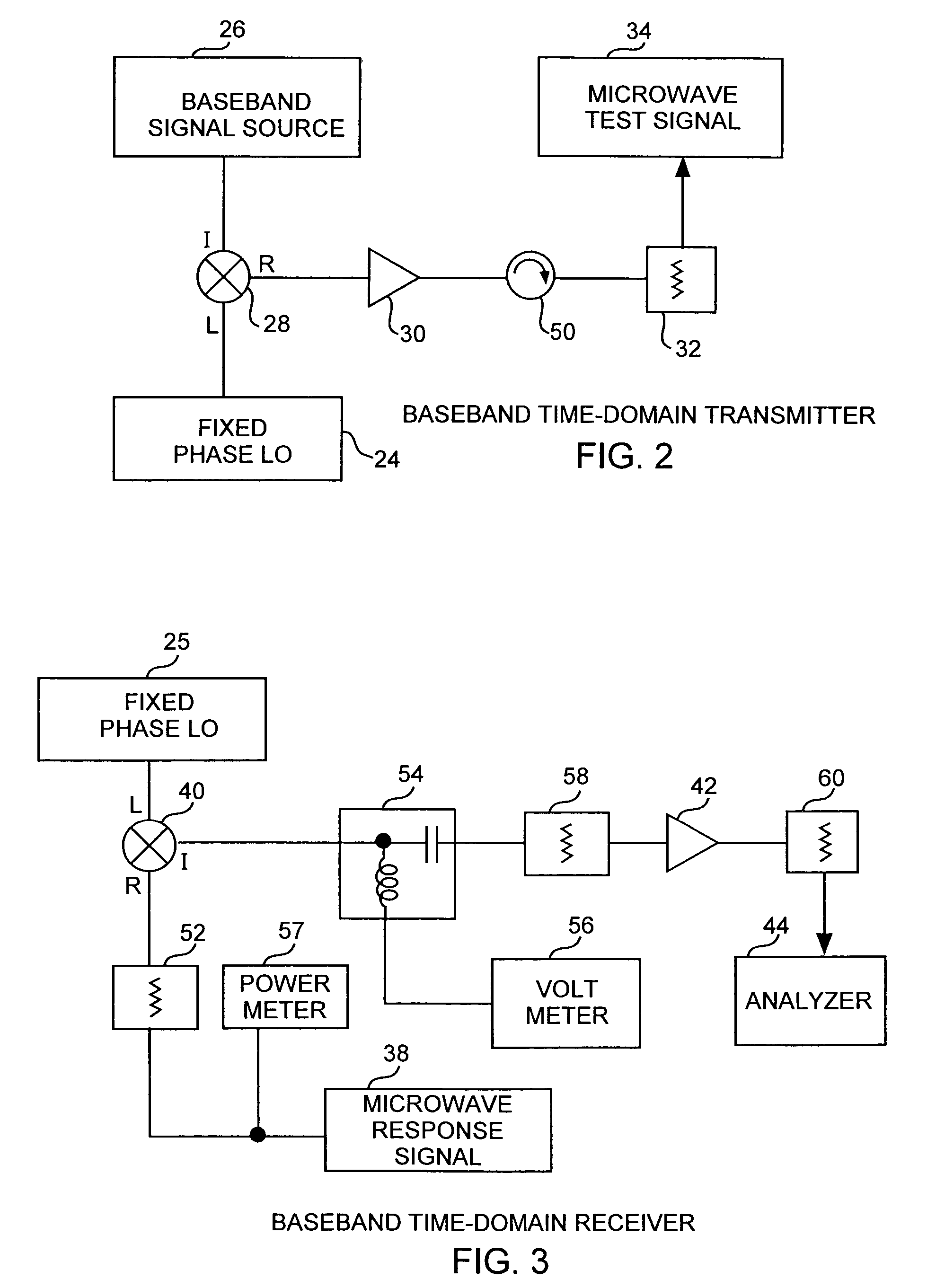
[0025]An embodiment of the invention is described with reference to the figures using reference designations as shown in the figures. Referring to FIGS. 1, 2 and 3, the baseband time-domain basic measurement test configuration system consists of an upconverting transmitter 10 and a downconverting receiver 12, both driven by a local oscillator generator 14, for measuring baseband waveforms. The oscillator generator 14 includes a local oscillator (LO) 16, a splitter 18 providing a local oscillator signal to an isolator 20 and phase shifter 22. The isolator 20 provides a fixed phase local oscillator signal 24 that may be considered as a carrier signal. The phase shifter 22 provides a variable phase local oscillator signal 25 that is used for coherent downconversion. In a broad form, the preferred transmitter 10 is driven by a baseband signal source 26 for providing a baseband test signal to the transmitter 10 and for providing a 10 MHz reference signal 27 and a trigger signal 59. The t...


PUM


Abstract

A communications system reduces downconverter inaccuracies in time-domain measurements or samples of received microwave communications I and Q complex signals by converting received signal to baseband taking measurements or samples of the I and Q waveforms at differing phase shifts of a demodulating carrier signal for a local oscillator or carrier tracking loop used during downconversion so that I and Q imbalances may be detected and removed by lowpass equivalent averaging for improved characterization of downconverters or for improved signal reception. In the preferred form, the phase shifts are 0 and π / 2 for a conventional measurement, and then at θ, and θ+π / 2, with θ=π / 4+mπ / 2 for an integer m for the second measurement where I and Q imbalances and baseband nonlinearities are indicated by differences between the two measured or sampled signals, where θ provides for optimum error detection for reducing the errors by averaging the measurements.

Description

FIELD OF THE INVENTION[0001]The invention relates to the field of measurement methods of electronic signals and devices. More particularly, the invention relates to baseband time-domain measurement methods of communications signals, such as modulated waveforms used in communication systems. Further still, the invention relates to methods for measuring the performance characteristics of nonlinear and linear devices used in communications systems such as power amplifiers used in transmitters. The invention further relates to receiver systems generating balanced baseband received signals for reducing imbalances in downconverters for improved signal reception.BACKGROUND OF THE INVENTION[0002]Modulated microwave signals are used to carry information in a wide variety of electronic communications systems. Examples include modulated microwave signals used to transmit voice and data or video signals from a ground transmitter through space to a satellite, and then back from the satellite to ...

Claims


Application Information

Patent Timeline
Patent Type & Authority Patents(United States)
IPC IPC(8): H03D3/22H04L27/22H04L27/38
CPCH04L27/3818H04L27/3863
Inventor MOULTHROP, ANDREW ALFREDMUHA, MICHAEL STEVENSILVA, CHRISTOPHER PATRICK
Owner THE AEROSPACE CORPORATION
Why Eureka
Try Eureka