Nitrogen monoxide, nitrogen dioxide and ozone determination in air

a technology of nitrogen dioxide and ozone determination, which is applied in the direction of material thermal analysis, withdrawal sample devices, material testing goods, etc., can solve the problems of complex system, high cost of devices, and £10,000 cos

Inactive Publication Date: 2008-01-29
CAMBRIDGE UNIV TECH SERVICES LTD
View PDF11 Cites 14 Cited by
  • Summary
  • Abstract
  • Description
  • Claims
  • Application Information

AI Technical Summary

Problems solved by technology

The resulting system is complex and the authors found it essential to pass incoming gas through scrubbers to remove ozone and to oxidise nitrogen monoxide to nitrogen dioxide before beginning irradiation.
However, these devices are expensive (in the order of £10,000), complex and suffer from limitation in stability with time and in response to temperature changes.
However, these devices are expensive (in the order of £10,000), complex and suffer from limitations, particularly relating to the quantitative conversion of nitrogen dioxide to nitrogen monoxide.
The fact that the sensor is attached to a balloon places severe restrictions in terms of weight and cost on the sensor design.
The cost aspect can be particularly critical, because generally such sensors have to be treated as disposable, given that they may be difficult to locate once they fall back to the ground.
All of this can make it extremely difficult to produce a sensor which provides appropriately accurate readings that are continuous throughout the ascent of the balloon and which is capable of resisting the effects of high altitude and low temperature, where contaminants such as rain ice can affect sensor output.
The pumps are expensive, relatively heavy and require considerable power to operate, increasing overall device weight.
Furthermore, with such sensors it can often be difficult to provide accurate readings because it is difficult to determine exactly the rate at which atmospheric air is flowing over the sensor and a further aim of the present invention is to provide sensing apparatus which mitigates this problem.

Method used


Image

  • Nitrogen monoxide, nitrogen dioxide and ozone determination in air
  • Nitrogen monoxide, nitrogen dioxide and ozone determination in air
  • Nitrogen monoxide, nitrogen dioxide and ozone determination in air

Examples


case 1

Sunlit Atmosphere:

[0070]Typically[O3]=50 ppb—in excess over NO[0071]J1=JSunlight (=10−2 s−1)[0072]τ=(10−2+5×10⁻⁴ [NO] (ppb))−1 s,.[0073]and so τ≦<100 secs

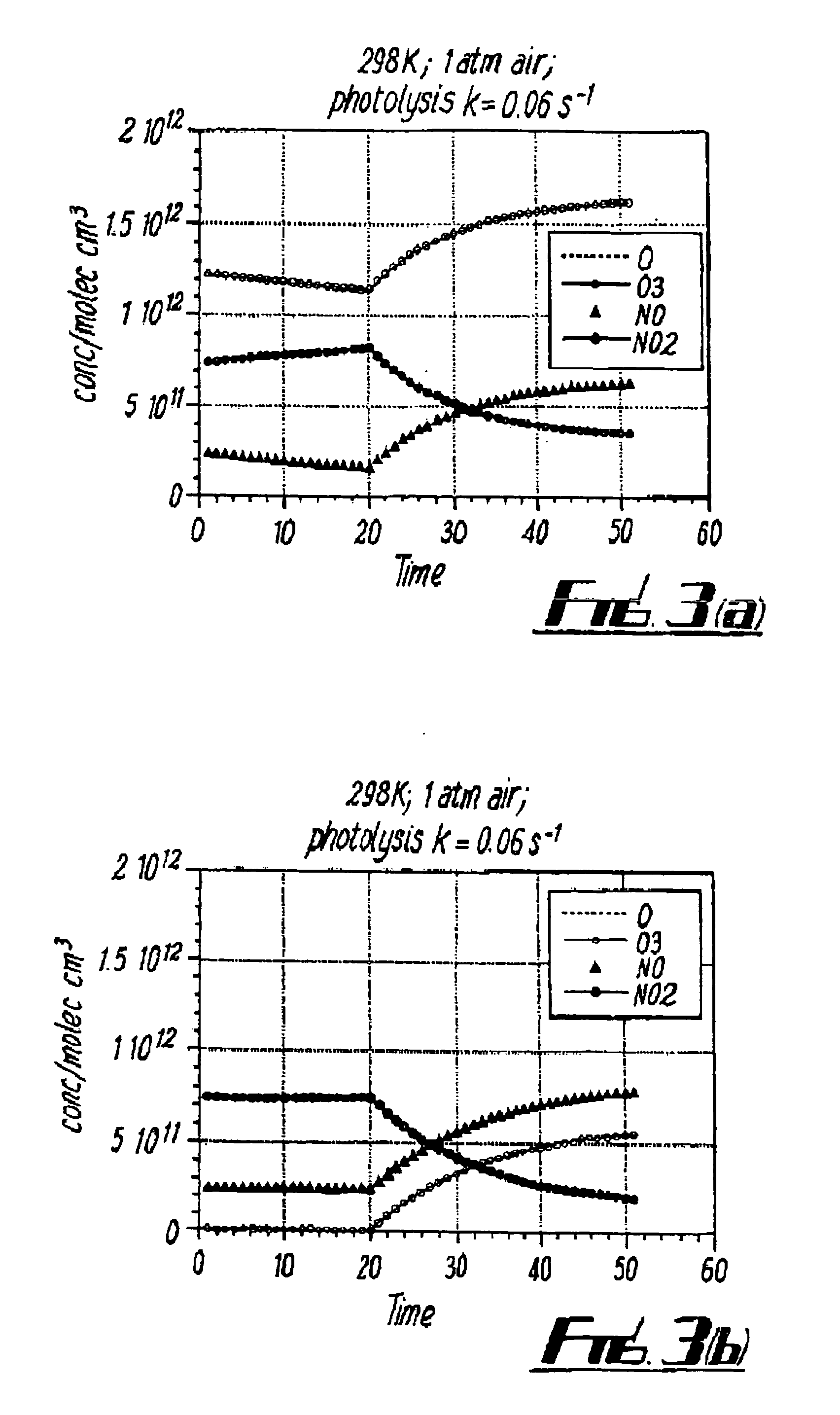
Case 2: In the Instrument Under Photolysis:[0074]J1=JNO2 (=0.1 s−1)[0075]τ=(10−1+5×10⁻⁴ [NO])1[0076]and so τ≦<10 secs

Case 3: In the Dark:[0077]J1=0

[0078]Therefore, in the dark, the atmospheric steady state relaxes towards a state where [NO] (or O3) tends to zero with τ=(5×10⁻⁴ [NO])−1 or(5×10⁻⁴[O3])−1 depending on which gas is present in excess. Therefore, typically τ>(2.5×10⁻²)−1 >≧40 secs.

[0079]If, however, concentrations of [NO] and [O3] are similar, it will be clear to one skilled in the art that you instead get a complex but mathematically definable rate of ozone loss.

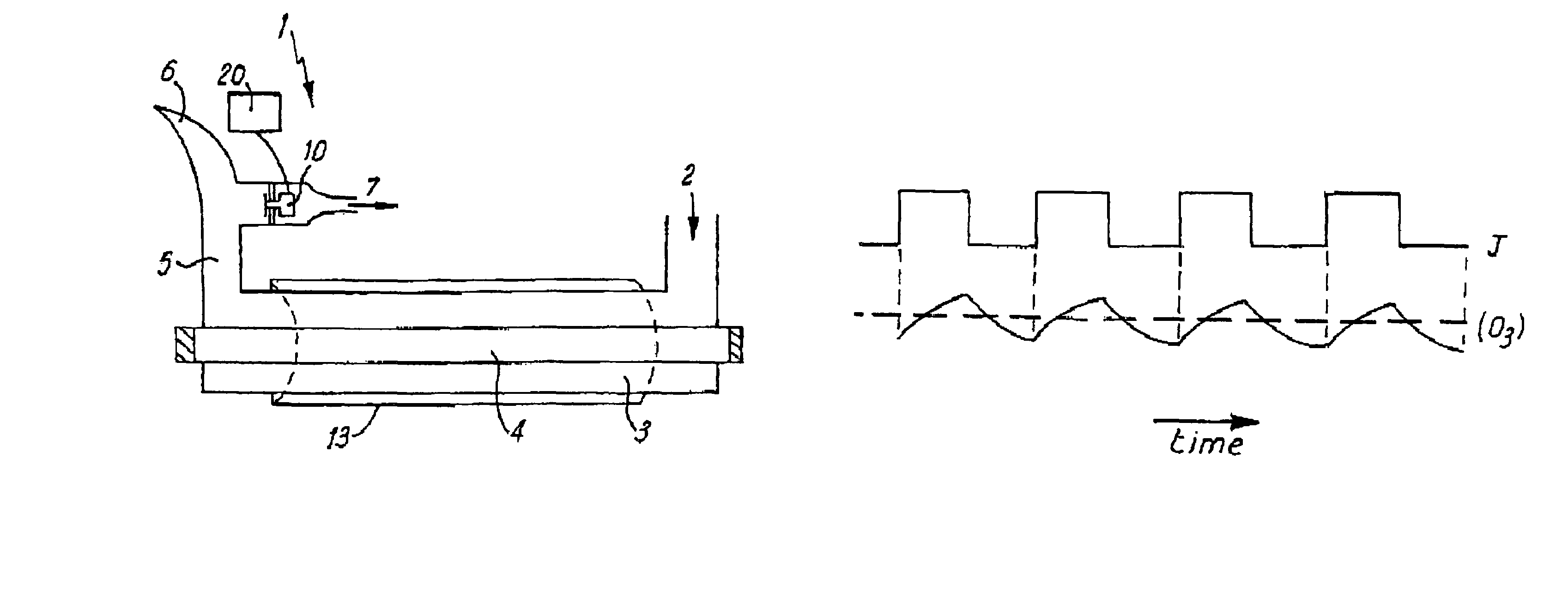
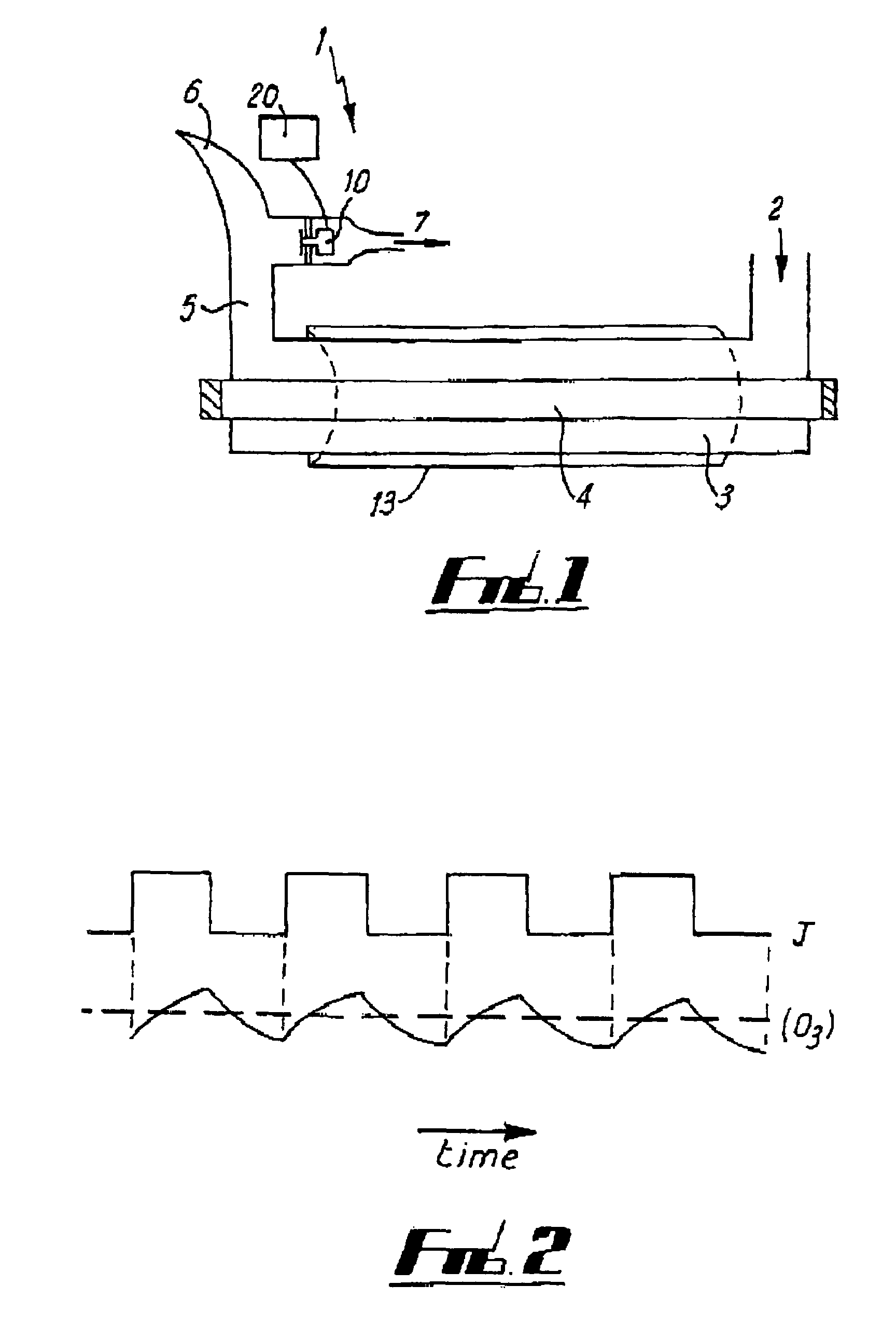
[0080]By monitoring the ozone concentration in response to periodic light and dark and application of standard computing techniques it is therefore possible to get information about all three components [O3], [NO2] and [NO].

[0081]In a preferred embodiment, light ...


PUM

PropertyMeasurementUnit
timeaaaaaaaaaa
concentrationaaaaaaaaaa
kinetic equilibriumaaaaaaaaaa

Abstract

An analytical system is provided for determining nitrogen monoxide, nitrogen dioxide and ozone concentrations in air samples. An ultraviolet light source 4 is used to alter the equilibrium between nitrogen dioxide and oxygen on the one hand and nitrogen monoxide and ozone on the other. Dynamic measurement of ozone concentration with time while ultraviolet irradiation is pulsed enables each gas concentration to be calculated without requiring input gases to be scrubbed. An aApparatus 101 is further provided to provide a controlled flow of gas to a sensor 103 attached to a high altitude balloon while sheltering it from the elements and allowing for affects of temperature, said apparatus comprising a shield 104 and a gas conducting means which uses the venturi effect to control air flow or has a hole to allow water to drain without affecting air flow past the sensor.

Description

STATEMENT OF RELATED APPLICATION[0001]This application is a continuation and claims the benefit of priority from U.S. patent application Ser. No. 09 / 774,157, filed Jan. 29, 2001, now abandoned, entitled “Air Content Determination”, which is incorporated herein by reference in its entirety.FIELD OF THE INVENTION[0002]This invention relates generally to devices and methods for the detection of atmospheric components and, in particular, to devices and methods for the detection of. Atmospheric components of particular interest are nitrogen dioxide, nitrogen monoxide and ozone.BACKGROUND[0003]In recent years, with increased concern over environmental issues, there is more and more need for accurate and cost effective measurement devices and methods for the detection of gases in the atmosphere. There is a demand both for measurements of pollutant gases at ground level, due to their direct effect on human health, and also within the atmosphere for atmospheric analysis and research.[0004]Oz...

Claims


Application Information

Patent Timeline
Patent Type & Authority Patents(United States)
IPC IPC(8): G01N33/00G01N27/407G01N1/22G01N21/76G01N27/04
CPCG01N27/123G01N33/0037G01N33/0039Y10T436/179228Y10T436/25875Y10T436/177692Y10T436/117497Y10T436/11Y10T436/178459Y10T436/206664Y02A50/20
Inventor COX, RICHARD ANTHONYJONES, RODERIC LEWIS
Owner CAMBRIDGE UNIV TECH SERVICES LTD
Why Eureka
Try Eureka