
Low drop-out voltage regulator with common-mode feedback

a voltage regulator and low dropout technology, applied in the field of voltage regulators, can solve the problems of limiting the capability of error amplifiers, ldo voltage regulator performance, and difficult stability of error amplifiers, and achieve the effect of stabilizing output voltage and increasing slew ra

Inactive Publication Date: 2008-01-29
O2 MICRO INT LTD
View PDF5 Cites 22 Cited by
  • Summary
  • Abstract
  • Description
  • Claims
  • Application Information

AI Technical Summary

Benefits of technology

"The invention is a circuit and method for regulating voltage using a low drop-out voltage regulator with common-mode feedback. The circuit includes an error amplifier, a pass device, a feedback circuit, and a compensation circuit. The method involves generating an amplified error voltage, driving the pass device with the amplified voltage, increasing the slew rate for the pass device, obtaining an output voltage, and providing frequency compensation to stabilize the output voltage. The technical effect of the invention is to provide a stable voltage output with low drop-out voltage regulation and common-mode feedback."

Problems solved by technology

The large parasitic capacitance between a gate terminal of the pass device and the AC ground, for example 100 pF or more, can limit the capability of the error amplifier, since the parasitic capacitance needs to be charged or discharged during a certain period in order to restore the output voltage of the LDO voltage regulator to a constant value.
The performance of the LDO voltage regulator is, therefore, greatly limited by the speed of the parasitic capacitance being charged and discharged which is defined a slew rate.
Additionally, the presence of the large parasitic capacitance can produce a significant pole in the frequency response of the error amplifier, which can result in the error amplifier more difficult to be stable.
However, the insertion of the dynamic bias circuit can increase the complexity of the LDO voltage regulator.
The insertion of the dynamic bias circuit may also create stability problems and cause the design of the LDO voltage regulator to become more complex.
In addition, the LDO voltage regulator generally has a lower efficiency due to a higher ground current consumed by the dynamic bias circuit.

Method used


Image

  • Low drop-out voltage regulator with common-mode feedback
  • Low drop-out voltage regulator with common-mode feedback
  • Low drop-out voltage regulator with common-mode feedback

Examples


Embodiment Construction

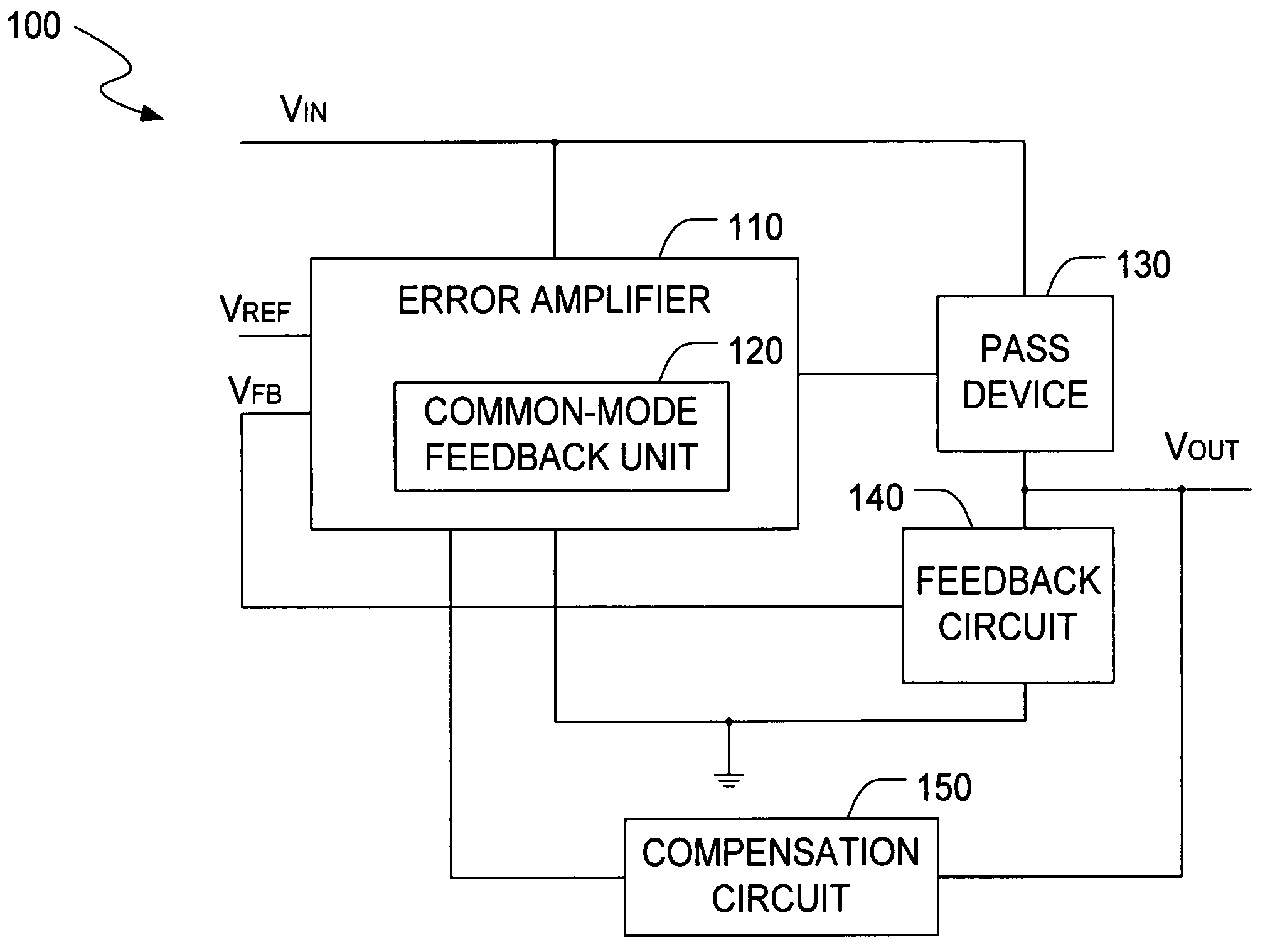
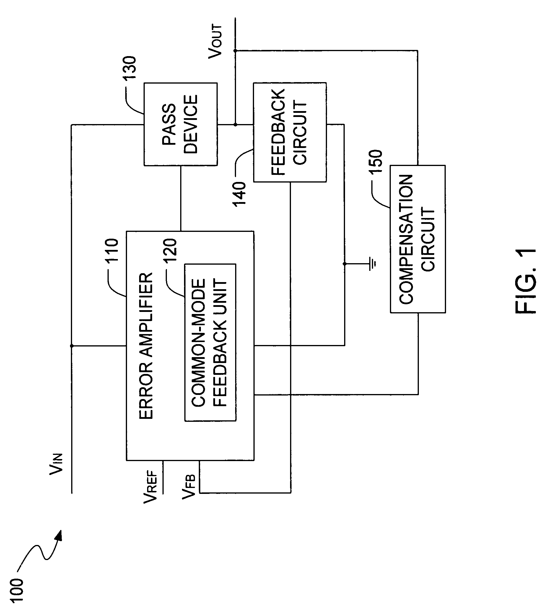
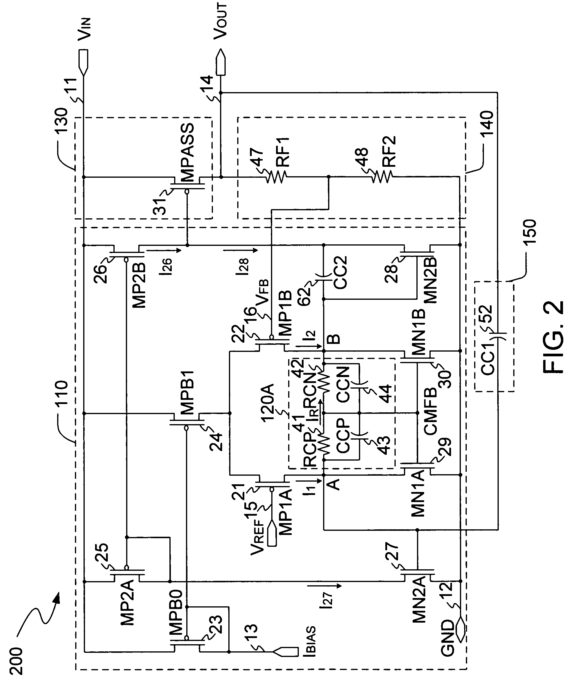
[0019]The invention provides a LDO voltage regulator with common-mode feedback, so that the LDO voltage regulator can quickly restore an output voltage to a stable condition when an external load varies in different conditions. FIG. 1 illustrates a block diagram of a LDO voltage regulator 100 with common-mode feedback. The voltage regulator 100 includes an error amplifier 110, a pass device 130, a feedback circuit 140, and a compensation circuit 150. The voltage regulator 100 can further include a common-mode feedback unit 120 to increase the response speed of the LDO structure through enlarging the slew rate for a gate voltage of a MOS transistor incorporated in the pass device 130. A power supply voltage VIN is provided to the error amplifier 110, and the pass device 130, respectively. The pass device 130 can provide an output voltage VOUT at an output terminal to an external load (not shown).

[0020]The error amplifier 110 can amplify a differential value between two input signals ...


PUM


Abstract

The present invention is a LDO voltage regulator circuit with common-mode feedback. The LDO voltage regulator includes an error amplifier with a common-mode feedback unit, a pass device and a compensation circuit. A signal from the pass device acts as an input signal to the error amplifier and is compared with another input signal, producing a differential signal. The differential signal is amplified and then provided to the pass device. A capacitor in the compensation unit provides frequency compensation to the LDO voltage regulator. The common-mode feedback unit incorporated into the error amplifier greatly improves a slew rate of a gate voltage of the pass device.

Description

RELATED APPLICATION[0001]This application claims the benefit of U.S. provisional application, titled Low-Voltage, Low Drop-out Voltage Regulator with a Common-Mode Feedback Operational Amplifier, Ser. No. 60 / 657,959, filed on Mar. 1, 2005, the specification of which is incorporated herein in its entirety by this reference.BACKGROUND OF THE INVENTION[0002]1. Field of the Invention[0003]The present invention relates to voltage regulator and in particular to a low drop-out voltage regulator with low power dissipation.[0004]2. Description of the Related Art[0005]Currently, the increasing demand for higher performance power supply circuits has resulted in a continued development of voltage regulator devices. Many low voltage applications, such as for use in cell phones, pagers, laptops, camera recorders and other mobile battery operated devices, require the use of low drop-out (LDO) voltage regulators. These portable electronics applications typically require low voltage and small quiesc...

Claims


Application Information

Patent Timeline
Patent Type & Authority Patents(United States)
IPC IPC(8): G05F1/575G05F1/565
CPCG05F1/575H03F3/345H03F3/45183H03F3/45659H03F2203/45424H03F2203/45248H03F2203/45404H03F2203/45418H03F2203/45008
Inventor TANG, XIAOHUWANG, WEIHOU, XIAOHUALIU, SHIQIANG
Owner O2 MICRO INT LTD
Learn More