Method and device for distance measurement

a technology of distance measurement and measurement method, which is applied in the direction of distance measurement, instruments, and using reradiation, etc., can solve the problems of excessive measurement expenditure, limit the range of measurement which can be measured with a specified measurement uncertainty,

Inactive Publication Date: 2008-01-29
ROBERT BOSCH GMBH
View PDF20 Cites 9 Cited by
  • Summary
  • Abstract
  • Description
  • Claims
  • Application Information

AI Technical Summary

Benefits of technology

[0022]In a likewise advantageous manner, the distance measurement device according to the invention is configurable such that the measurement time, the measurement uncertainty of the measurement and the resolution of the measured result are selectable individually or as a whole. A user of the measurement device according to the invention can enter a fixed measurement time or a desired accuracy for the distance measurement using an operating field, for example. The electronics in the measurement device then adjust, semi-automatically, the remaining measurement parameters via corresponding circuit means in such a manner that the desired measurement uncertainty and/or the desired measurement time are made possible.
[0023]The measurement device accordi

Problems solved by technology

For small reflected signals, which occur when measurement distances are great or when a measurement is taken against surfaces with low reflectance, this results in a limitation of the measuring range which can be measured with a specified measurement uncert

Method used


Image

  • Method and device for distance measurement
  • Method and device for distance measurement
  • Method and device for distance measurement

Examples


Embodiment Construction

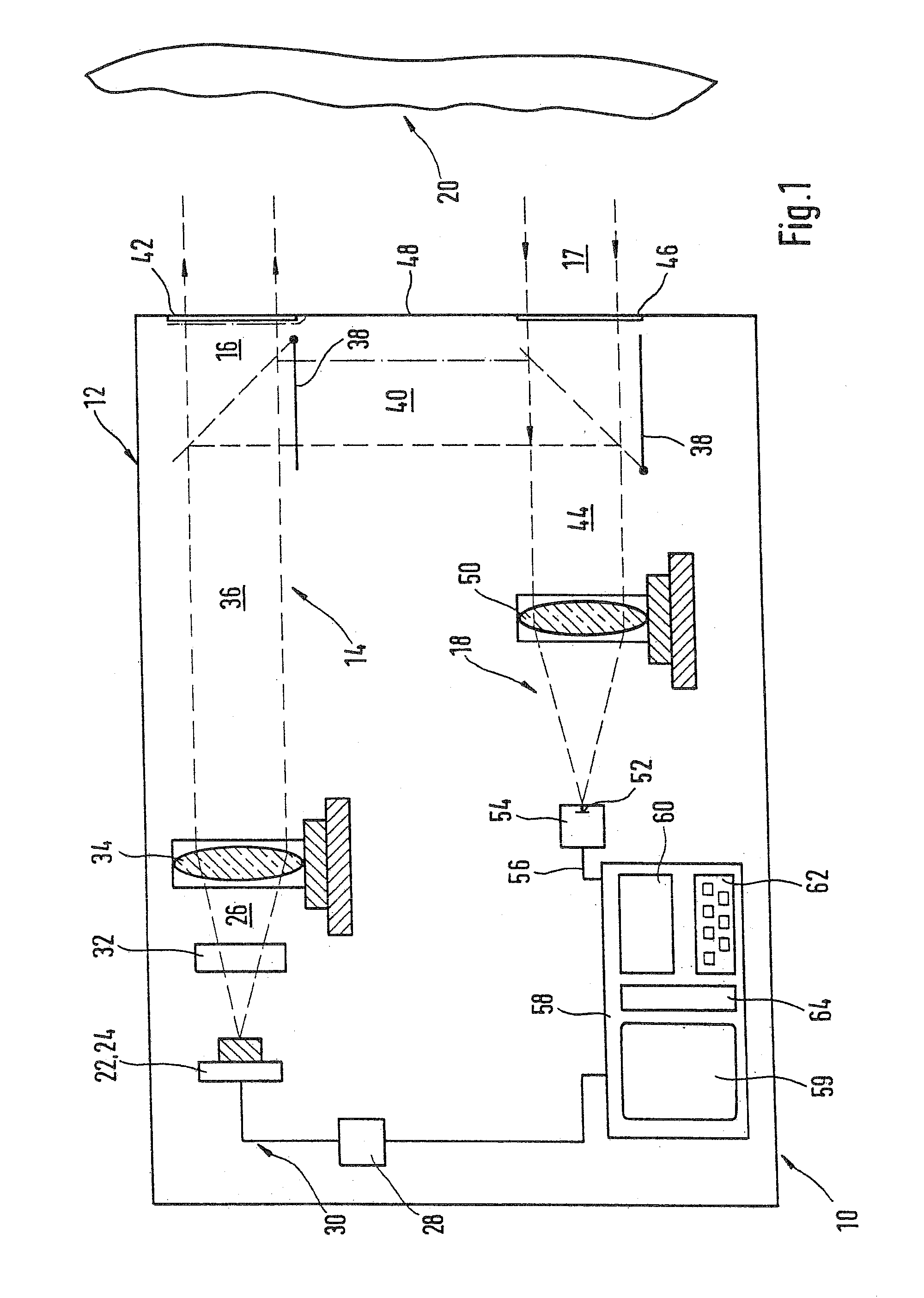
[0044]FIG. 1 shows, in schematic fashion, a distance measurement device 10 according to the general class with the most important components for describing its basic configuration. Device 10 has a housing 12 in which a transmission branch 14 for generating a measurement signal 16 and a receive branch 18 for detecting the measurement signal 17 returning from a target object 20 are located. Receive branch 18 forms a receive channel for returning measurement signal 17.

[0045]Transmit branch 14 contains a light source 22, which is realized in the exemplary embodiment in FIG. 1 by a semiconductor laser diode 24. The use of other light sources and non-optical transmitters in the device according to the invention is also possible.

[0046]Laser diode 24 in the exemplary embodiment according to FIG. 1 emits a laser beam in the form of a light bundle 26 that is visible to the human eye. Laser diode 24 is operated via a control device 28 which, using corresponding electronics, generates a modulat...


PUM


Abstract

The present invention relates to a device (10) for distance measurement, with at least one transmitting branch (14) with a transmission source (22, 24) for a measurement signal for emitting a modulated measuring beam (16, 26, 36) in the direction of a target object (20), and with a receive branch (18) for the measurement radiation (17, 44) returning from the target object (30), and with a control and evaluation unit (28, 58) for determining the distance of the device (10) to the target object (20) from the measurement radiation returning from the target object (20).
It is proposed according to the invention that the device (10) include means that enable measurement of distances with predetermined measurement uncertainties.
The present invention further relates to a method for distance measurement, with which a measurement of distances with predetermined measurement uncertainties is possible. To ensure a distance measurement in a certain, predetermined measurement time, the value on which a distance measurement is based can be adjusted to the measurement uncertainty, and can be increased incrementally in particular.

Description

CROSS-REFERENCE[0001]The invention described and claimed hereinbelow is also described in PCT / DE 03 / 01522, filed on May 12, 2003 and DE 102 32 878. 1, filed Jul. 19, 2002. This German Patent Application, whose subject matter is incorporated here by reference, provides the basis for a claim of priority of invention under 35 U.S.C. 119 (a)-(d).BACKGROUND OF THE INVENTION[0002]The present invention is directed to a device for distance measurement and / or a method for distance measurement.[0003]Distance measurement devices and, in particular, optical distance measurement devices as such have been known for some time. These devices emit a modulated measuring beam, e.g., a light or laser beam, which is directed to a desired target object, the distance of which to the device is to be determined. A portion of the returning measurement signal that is reflected or scattered by the sighted target object is detected again by the device and used to determine the sought-after distance.[0004]A dist...

Claims


Application Information

Patent Timeline
IPC IPC(8): G01C3/08G02B27/40G01C15/00G01S7/48G01S7/491G01S7/493G01S7/497G01S17/08G01S17/36
CPCG01C15/002G01S7/491G01S7/493G01S17/36G01S7/497G01S13/08
Inventor STIERLE, JOERGWOLF, PETERFLINSPACH, GUNTER
Owner ROBERT BOSCH GMBH
Why Eureka
Try Eureka