Piezoelectric/electrostrictive element and method for manufacturing thereof

Active Publication Date: 2010-12-30
NGK INSULATORS LTD
View PDF4 Cites 15 Cited by
  • Summary
  • Abstract
  • Description
  • Claims
  • Application Information

AI Technical Summary

Benefits of technology

[0010]To decrease the number of firing times and simplify manufacturing steps, for example, a cermet paste is applied onto an unfired piezoelectric / electrostrictive body (a piezoelectric / electrostrictive precursor), and then the piezoelectric / electrostrictive body and external terminal electrodes are simultaneously fired in a lump. In this case, a piezoelectric / electrostrictive material contained in the cermet paste is deposited on the surface of the formed external terminal electrodes sometimes. The deposited piezoelectric / electrostrictive material is usually an insulator, and hence the conducting performance of the external terminal electrodes might become insufficient. Furthermore, when electric characteristics of a product having such an external terminal electrodes are evaluated, it has been sometimes judged that the measurement of the conductivity is impossible due to difficulty in acquiring the conductivity.
[0012]The present invention has been developed in view of such problems of a conventional technology, and an object thereof is to provide an inexpensively manufacturable piezoelectric / electrostrictive element possessing the external terminal electrodes excellent in the conducting performance, which is satisfactorily adhered tightly to a piezoelectric / electrostrictive body and does not peel easily therefrom, and a manufacturing method thereof.
[0025]The piezoelectric / electrostrictive element according to the present invention can show such an effect that the piezoelectric / electrostrictive element possesses the external terminal electrodes excellent in the conducting performance, which adhere to the piezoelectric / electrostrictive body in such a satisfactory state so that they do not easily peel from the piezoelectric / electrostrictive body, and that it is producible in a low price.
[0026]Moreover, according to the present inventive method for manufacturing a piezoelectric / electrostrictive element can show such an effect that it is possible to simply and inexpensively manufacture the piezoelectric / electrostrictive element possessing the external terminal electrode excellent in the conducting performance, which does not easily peel from the piezoelectric / electrostrictive body, and adheres tightly thereto.

Problems solved by technology

In this case, a piezoelectric / electrostrictive material contained in the cermet paste is deposited on the surface of the formed external terminal electrodes sometimes. The deposited piezoelectric / electrostrictive material is usually an insulator, and hence the conducting performance of the external terminal electrodes might become insufficient.
Furthermore, when electric characteristics of a product having such an external terminal electrodes are evaluated, it has been sometimes judged that the measurement of the conductivity is impossible due to difficulty in acquiring the conductivity.
On the other hand, in a case where an electrode material which does not contain the piezoelectric / electrostrictive material is used on the piezoelectric / electrostrictive precursor to avoid the deposition of the piezoelectric / electrostrictive material on the surface of the external terminal electrode, adhesion of the formed external terminal electrode and the piezoelectric / electrostrictive body become insufficient, thereby causing a problem that the external terminal electrode easily peels from the piezoelectric / electrostrictive body during or after firing.
Moreover, in a case where a material containing an added glass component is used as an external terminal electrode material to avoid the peeling of the external terminal electrodes from the piezoelectric / electrostrictive body, when the piezoelectric / electrostrictive body and the external terminal electrodes are formed by simultaneous firing, a piezoelectric / electrostrictive porcelain composition reacts with a glass component, and the composition of the piezoelectric / electrostrictive porcelain composition fluctuates, thereby causing a problem that the characteristics of the obtained piezoelectric / electrostrictive body are deteriorated.

Method used


Image

  • Piezoelectric/electrostrictive element and method for manufacturing thereof
  • Piezoelectric/electrostrictive element and method for manufacturing thereof
  • Piezoelectric/electrostrictive element and method for manufacturing thereof

Examples


examples

[0104]Hereinafter, the present invention will specifically be described with respect to examples, but the present invention is not limited to these examples.

[0105](Manufacturing of Piezoelectric / Electrostrictive Porcelain Composition)

[0106]Materials, i.e., 68.5 mass % of PbO, 11.7 mass % of TiO2, 17.5 mass % of ZrO2, 0.90 mass % of Sb2O3, 0.82 mass % of Nb2O5 and 0.60 mass % of MnCO3 in terms of MnO2 were weighed, and mixed with the predetermined amount of water for 24 hours by a ball mill to obtain a prepared slurry. The resultant prepared slurry was placed in a hot-air drier to evaporate the water, followed by drying, to obtain the mixed material. The resultant mixed material was placed in a sheath made of magnesia, the sheath was closed with a cover made of magnesia, and the material was heated and calcinated at 1000° C. in an electric furnace to obtain a calcinated material. The resultant calcinated material was ground with the predetermined amount of the water by the ball mill ...

reference examples 1 to 18

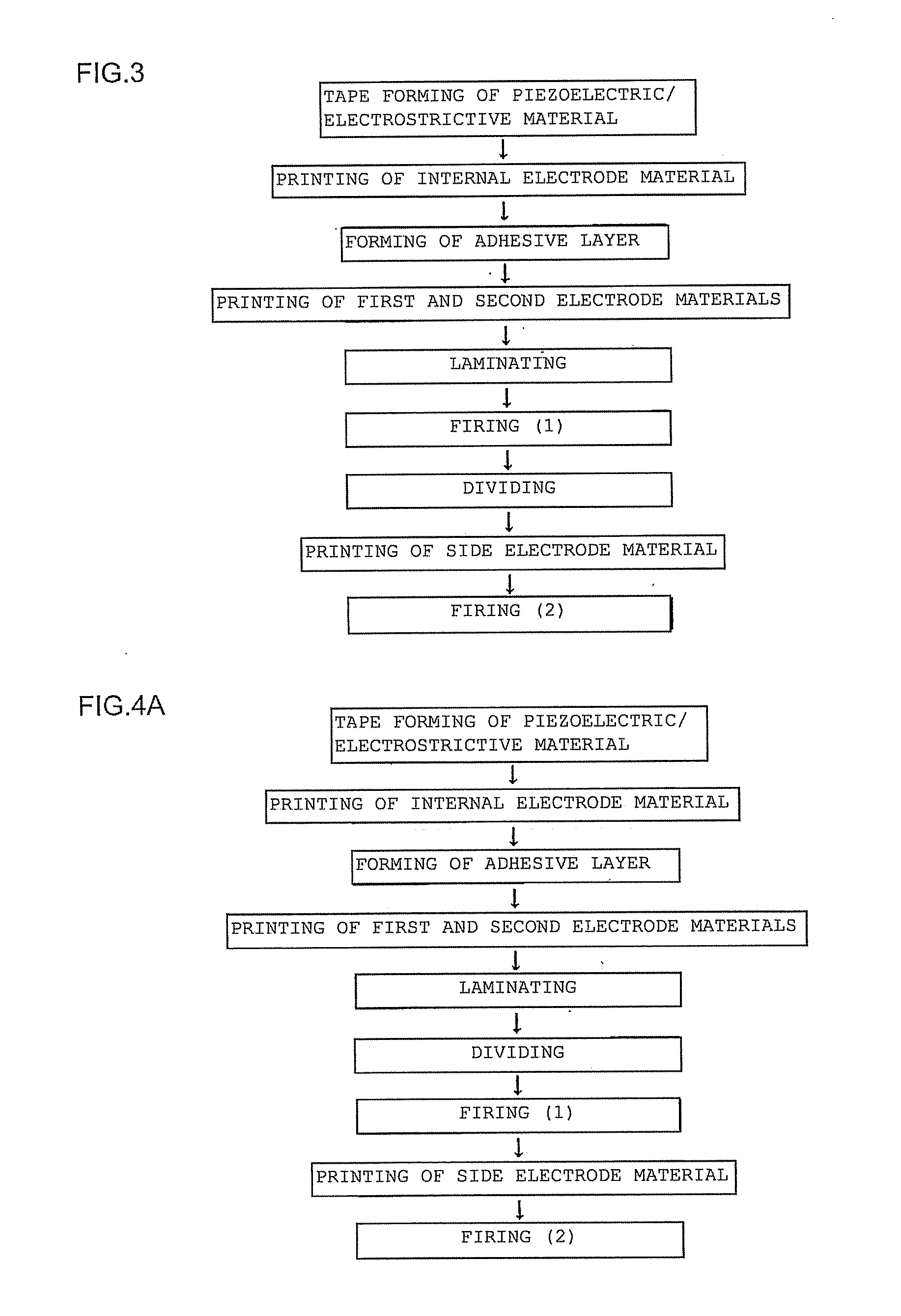
[0109]A piezoelectric / electrostrictive porcelain composition, a dispersant, a plasticizer and a solvent were mixed to prepare a slurry, and tape forming was performed by a doctor blade method, to prepare a green sheet. It is to be noted that the thickness of the prepared green sheet was designed so that the thickness thereof became 36 μm after firing. On the green sheet, a pasted electrode material containing a metal component shown in Table 1 (Ag—Pd coprecipitation powder prepared by a coprecipitation method, Ag—Pd allow powder or Pt) was printed in a predetermined shape by a screen printing method. It is to be noted that the electrode material was printed so that the thickness thereof became 1.5 μm after the firing. Furthermore, on the electrode material, an adhesive layer was printed so that the thickness thereof became 2.0 μm after the firing.

[0110]The printed green sheets for 30 layers were laminated and thermo compression bonded to prepare a laminated substrate including 100 (...

example 1

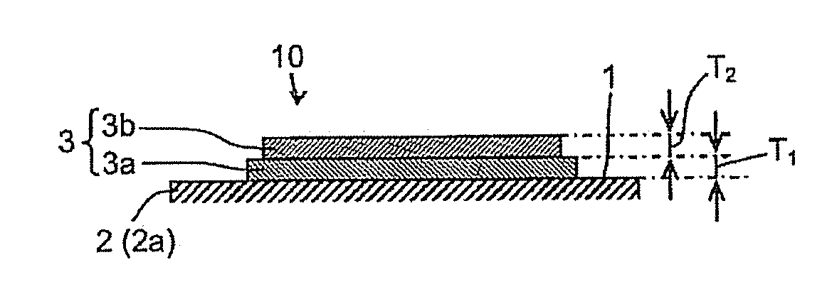
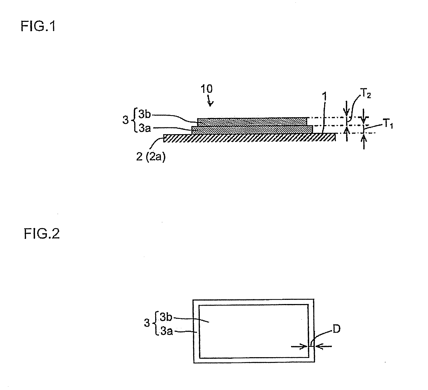
[0112]A piezoelectric / electrostrictive porcelain composition, a dispersant, a plasticizer and a solvent were mixed to prepare a slurry, and tape forming was performed by a doctor blade method, to prepare a green sheet. On the green sheet, a pasted first electrode material containing 97 mass % of Ag—Pd alloy powder (Ag:Pd=7:3 (mass ratio)) and 3 mass % of piezoelectric / electrostrictive porcelain composition (with the proviso that the total of Ag—Pd alloy powder and the piezoelectric / electrostrictive porcelain composition=100 mass %) was printed in a predetermined shape by a screen printing method. It is to be noted that the first electrode material was printed so that a thickness T1 (see FIG. 1) of the formed first electrode layer was 5.0 μm after the firing. Next, on the printed first electrode material, a pasted second electrode material containing Ag—Pd alloy powder (Ag:Pd=7:3 (mass ratio)) was printed in a predetermined shape by the screen printing method. It is to be noted that ...


PUM

PropertyMeasurementUnit
Percent by massaaaaaaaaaa

Abstract

Disclosed is a piezoelectric / electrostrictive element equipped with a piezoelectric / electrostrictive drive unit having a piezoelectric / electrostrictive body, and a film external terminal electrode containing substantially no glass component and being disposed on at least one surface of the piezoelectric / electrostrictive body. The external terminal electrode is an electrode having a laminated structure equipped with a first electrode layer made of a first electrode material being disposed to contact the piezoelectric / electrostrictive body closely and containing a first metal component and a piezoelectric / electrostrictive material, and a second electrode layer made of a second electrode material containing a second metal component and substantially no piezoelectric / electrostrictive material, which the first and second metal components are in the same element system.

Description

TECHNICAL FIELD[0001]The present invention relates to a piezoelectric / electrostrictive element suitable as an ultrasonic motor or the like, and a method for manufacturing thereof.BACKGROUND ART[0002]A laminated type piezoelectric / electrostrictive element conventionally manufactured by use of a piezoelectric / electrostrictive material (hereinafter referred to also as a piezoelectric / electrostrictive porcelain composition, a piezoelectric / electrostrictive ceramics or the like) has been utilized for electronic products such as a piezoelectric actuator, a filter, a piezoelectric resonator (including an oscillator), an ultrasonic vibrator, an ultrasonic motor and a piezoelectric sensor since the element has a very high response speed in an electric signal.[0003]As a related conventional technology, in Patent Document 1, there is disclosed a laminated type piezoelectric actuator having been obtainable an insulator, external electrodes and lead wires on a fired body produced by firing a lam...

Claims


Application Information

Patent Timeline
IPC IPC(8): H01L41/047H01L41/18H01L41/22H01L41/273H01L41/29H01L41/293H01L41/39
CPCC04B35/491Y10T29/42C04B2235/3251C04B2235/3256C04B2235/3258C04B2235/3262C04B2235/3267C04B2235/3281C04B2235/3294C04B2235/36C04B2235/5445C04B2235/6025H01L41/047H01L41/0472H01L41/107H01L41/1876H01L41/273H01L41/29H01L41/293C04B2235/3244H10N30/87H10N30/872H10N30/877H10N30/40H10N30/8554H10N30/063H10N30/06H10N30/053
Inventor UETANI, MASAYUKIITO, HARUHIKO
Owner NGK INSULATORS LTD
Why Eureka
Try Eureka