Vibrating gyroscopic sensor and method of adjusting vibrating gyroscopic sensor

a vibrating gyroscopic sensor and vibration technology, applied in the field of vibration gyroscopic sensor and method of adjusting vibrating gyroscopic sensor, can solve the problems of loss of stable piezoelectric properties, extreme difficulty in employing the above-described method of adjusting a known vibrating gyroscopic sensor, etc., to prevent the change in the quality of the piezoelectric film during adjustment, maintain the strength and durability of the vibrator against dropping impact, and adjust the vibration characteristics of the vibr

Active Publication Date: 2008-02-05
SONY CORP
View PDF6 Cites 9 Cited by
  • Summary
  • Abstract
  • Description
  • Claims
  • Application Information

AI Technical Summary

Benefits of technology

[0017]The laser processing area on the vibrator faces the upper or a side surface of the vibrating gyroscopic sensor element mounted on the support substrate, the vibration characteristic of the vibrator can be easily adjusted by irradiating the laser processing area with a laser beam. Since the vibration characteristic is adjusted after the vibrator is mounted on the support substrate, the vibration characteristic can be prevented from showing a change from before to after mounting and each individual vibrating gyroscopic sensor element can be adjusted within an operational range after mounting by observing the vibration characteristic after mounting.
[0018]The laser processing area refers to a surface opposing the first surface where the piezoelectric film and so on are provided or the ridge line area connecting these surfaces. Accordingly, since the laser processing area is an area a distance apart from the first surface, changes in the piezoelectric quality and / or the polarization state due to heat generated during laser processing can be prevented as must as possible.
[0021]The effect of the adjustment depends on the position of the section to be laser-processed. Since the amount of change in the frequency difference and the detection signal balance becomes smaller as the section to be laser-processed moves from the base of the vibrator to the tip, course adjustment can be carried out by processing the base and fine adjustment can be carried out by processing the tip. By controlling the position of the section to be laser-processed and the depth of the laser processing, the strength and durability of the vibrator against dropping impact can be maintained.
[0022]As described above, for a vibrator of a vibrating gyroscopic sensor element mounted on a support substrate according to an embodiment of the present invention, a depression for adjusting the vibration characteristics is formed in an area excepting the surface of the vibrator on which the piezoelectric layer and so on are provided. Therefore, it is possible to adjust the vibration characteristics of the vibrator after the vibrator is mounted and change in the quality of the piezoelectric film during adjustment can be prevented.
[0023]Since the vibration characteristics are adjusted by carrying out laser processing on a surface of the vibrator on which the piezoelectric film and so on are disposed, the small vibrating gyroscopic sensor element produced through a semiconductor process can maintain stable detection ability and high durability against external impacts while fine and accurate adjustment can be easily carried out.

Problems solved by technology

However, it is extremely difficult to employ the above-described method of adjusting a known vibrating gyroscopic sensor to a fine, small vibrating gyroscopic sensor that is produced by employing a semiconductor process.
Furthermore, there is a possibility that the piezoelectric film and the various electrode films provided on the surface of the vibrator will be damaged when adjusting the vibration of a fine, small vibrating gyroscopic sensor, causing the loss of stable piezoelectric properties.

Method used


Image

  • Vibrating gyroscopic sensor and method of adjusting vibrating gyroscopic sensor
  • Vibrating gyroscopic sensor and method of adjusting vibrating gyroscopic sensor
  • Vibrating gyroscopic sensor and method of adjusting vibrating gyroscopic sensor

Examples


first embodiment

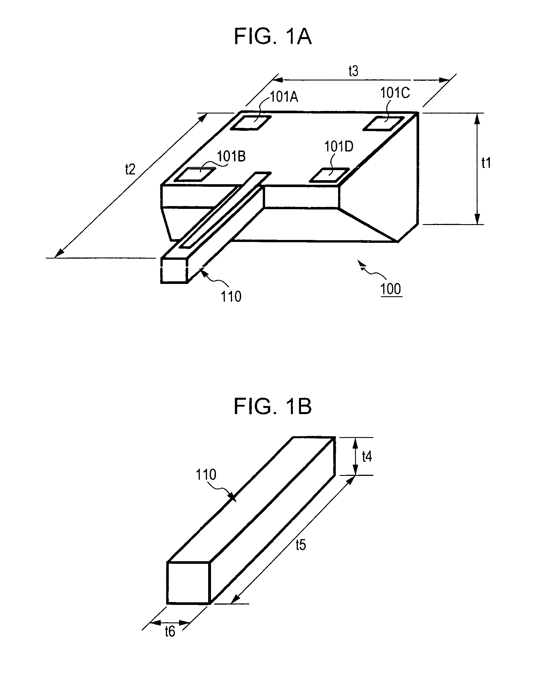
[0100]FIGS. 1A and 1B illustrate a vibrating gyroscopic sensor element 100 according to an embodiment of the present invention. FIG. 1A is an external perspective view illustrating the entire vibrating gyroscopic sensor element 100. FIG. 1B is an enlarged perspective view of a vibrator 110 of the vibrating gyroscopic sensor element 100. As shown in FIGS. 1A and 1B, the vibrating gyroscopic sensor element 100, cut out from a silicon single-crystal substrate, includes the cantilever vibrator 110 that is provided as a cantilever. This cantilever vibrator 110 is shaped as a prism, and, thus, a cross-section of the cantilever vibrator 110 orthogonal to the longitudinal direction of the cantilever vibrator 110 is square.

[0101]The vibrating gyroscopic sensor element 100 has a thickness t1 of 300 μm, a length t2 of 3 mm, and a width t3 of 1 mm. The cantilever vibrator 110 that actually vibrates has a thickness t4 of 100 μm, a length t5 of decorative panel 2.5 mm, and a width t6 of 100 μm. T...

second embodiment

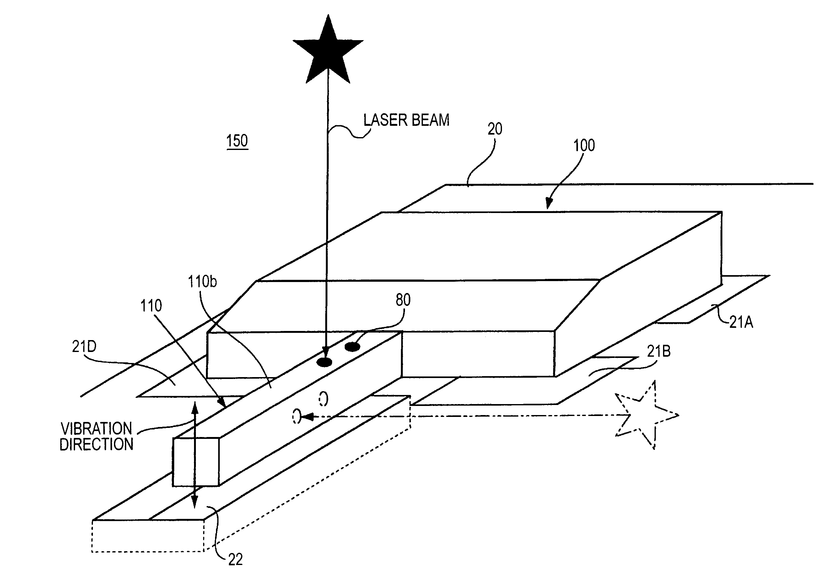
[0198]As described above, to adjust a vibrating gyroscopic sensor element according to an embodiment of the present invention, laser processing is carried out on the rear surface 110b of a cantilever vibrator 110 included in a vibrating gyroscopic sensor element 100 mounted on a support substrate 20, as shown in FIG. 3, to a degree so that the target vibration characteristics are obtained.

[0199]There are mainly two items of the cantilever vibrator 110 to be adjusted: the frequency difference between the vertical resonance frequency and the horizontal resonance frequency and the difference in the magnitudes of the left and right detection signals. By adjusting the frequency difference, the sensitivity of the sensor can be improved, whereas by adjusting the difference in left and right detection signals, noise of the sensor can be reduced.

[0200]In the above-described first embodiment, the magnitudes of the left and right detection signals when the cantilever vibrator 110 vibrates at a...

third embodiment

[0210]As described above, a vibrating gyroscopic sensor according to an embodiment of the present invention includes vibrating gyroscopic sensor elements 100A and 100B that have the same configuration and are mounted on the same support substrate in different axial direction. In this way, the vibrating gyroscopic sensor is capable of detecting angular rates in two axial directions (refer to FIG. 40). The vibrating gyroscopic sensor includes electronic components, such as IC chips, on the same support substrate. In addition, the vibrating gyroscopic sensor is set inside a main body including various sensor components and electronic devices. Therefore, it is necessary to improve the accuracy of the sensor output by preventing cross talk between the pair of vibrating gyroscopic sensor elements, between components, such as IC components, on the support substrate, and between the electronic devices included in the main body.

[0211]To adjust the level of detuning and adjust the detection s...


PUM

PropertyMeasurementUnit
width t3aaaaaaaaaa
length t2aaaaaaaaaa
thickness t1aaaaaaaaaa

Abstract

A vibrating gyroscopic sensor including a vibrating gyroscopic sensor element including a cantilever vibrator that includes a piezoelectric film, a driving electrode, and a pair of detection electrodes on a first surface, and a support substrate on which the vibrating gyroscopic sensor element is mounted. The vibrating gyroscopic sensor element is mounted on the support substrate so that the first surface of the cantilever vibrator faces the support substrate. An area other than the first surface of the cantilever vibrator is defined as a laser processing area where a depression for adjusting the vibration characteristics of the cantilever vibrator is to be provided.

Description

CROSS REFERENCES TO RELATED APPLICATIONS[0001]The present invention contains subject matter related to Japanese Patent Applications JP 2005-106717, JP 2005-176871, JP 2005-176870, and JP 2005-380330 filed in the Japanese Patent Office on Mar. 4, 2005, Jun. 16, 2005, Jun. 16, 2005, and Dec. 28, 2005, respectively, the entire contents of which are incorporated herein by reference.BACKGROUND OF THE INVENTION[0002]1. Field of the Invention[0003]The present invention relates to an angular rate sensor used for, for example, shaking detection in a video camera, motion detection in a virtual reality apparatus, or direction detection in a car navigation system and, more specifically, relates to a small vibrating gyroscopic sensor including a cantilever vibrator and a method of adjusting the same.[0004]2. Description of the Related Art[0005]As a known commercial angular rate sensor, a vibrating gyroscopic sensor that is configured to detect angular rate by vibrating a cantilever vibrator at a...

Claims


Application Information

Patent Timeline
Patent Type & Authority Patents(United States)
IPC IPC(8): G01P3/00G01P9/00G01C19/56G01C19/5656G01C19/5663H01L41/08H01L41/18H01L41/22H01L41/253
CPCG01C19/5663Y10T29/49002G01C19/5614G01C19/5698G01C19/5726
Inventor TAKAHASHI, KAZUOINAGUMA, TERUOAIZAWA, MANABUSUZUKI, KOJISASAKI, SHINNAKASHIO, EIJI
Owner SONY CORP
Why Eureka
Try Eureka