Solder heating system

a heating system and a technology of asolder, applied in the direction of metal working equipment, manufacturing tools, and soldering apparatus, can solve the problems of clogging of the vacuum source, shortening the desoldering operation, and requiring frequent cleaning or changing of the solder collection chamber, so as to minimize the resistance to prevent the flow of melted solder. , the effect of easy replacement and maintenance of the desoldering tool

Active Publication Date: 2008-02-05
HAKKO CO LTD
View PDF17 Cites 3 Cited by
  • Summary
  • Abstract
  • Description
  • Claims
  • Application Information

AI Technical Summary

Benefits of technology

[0006]This invention provides a heating system capable of melting solder and removing the melted solder away from a substrate. The heating system includes a desoldering tool having at least a first handle and a second handle. Dividing the desoldering tool into two handles allows an operator to use the desoldering tool in two ways. One way is to operate the first handle independently without the second handle. Another way is to couple the second handle tangentially to the first handle so that an operator can grip the second handle like a pistol. The desoldering tool offers two ways to grip the tool so that operator can grip the first handle or the second handle depending on the operator's preference.
[0007]The first handle has a front end and a back end. Along the front end, the first handle is adapted to receive a heater cartridge. The heater cartridge has a leading section with a tip with a channel within the leading section to convey the vacuum source to the tip. In the back end, the first handle receives a power source and a vacuum source, where the power is transmitted to a heater, adjacent to the tip, to convert the power to heat in order to heat the tip. A passage between the vacuum source and the front end of the first handle conveys the vacuum source to the channel within the leading section. This allows the tip to heat the solder and retrieve the melted solder with the vacuum source provided through the channel formed within the leading section. To minimize the resistance to flow of the melted solder, the length of the channel may be minimized and the channel may be substantially straight. In addition, the temperature along the channel may be substantially constant.
[0010]The first handle may have a cavity adapted to releaseably receive a storage, where the melted solder through the channel can be deposited and stored. The storage may include a filter to capture the dust or vapors from the melted solder that may clog up the passage to the vacuum source in the first handle. The storage may have a divot adapted to receive a key from the first handle so that the storage may be orientated in a predetermined position relative to the cavity. The cavity in the first handle is exposed so that the storage can be readily inserted or replaced. This allows the operator to easily replace and maintain the desoldering tool without significant downtime.
[0011]Besides the leading section, the heater cartridge may have an electrical cartridge that couples to the power source to provide power to the heater adjacent to the tip. The heater cartridge has a transition section to couple the leading section to the electrical cartridge so that the longitudinal axis of the leading section is staggered with the longitudinal axis of the electrical cartridge. Such configuration allows the leading section to have a shortened channel that is substantially straight and aligned with the passage formed within the first handle to minimize the resistance to flow of the melted solder and provide an efficient path for the vacuum source. The diameter of the channel may be greater away from the tip to minimize the resistance to flow of the melted solder. In addition, the heater and the leading section may be integrated by bonding the two with ceramic material. This is done to block out air gaps to improve the conduction path from the heater to the tip of the leading section. By improving the conduction or heat transfer from the heater to the tip, the leading section may have a better thermal recovery to rapidly heat the leading tip and the channel.

Problems solved by technology

As the melted solder quickly fills the solder collection chamber, the passage to the vacuum source can clog up.
This can shorten the desoldering operation and require frequent cleaning or changing of the solder collection chamber.
This adds to the downtime of the desoldering operation and increases the chance that the desoldering tool is reassembled improperly.
The frequent exchange or cleaning of the solder collection chamber also adds to the cost of operating the desoldering tool because of the expense associated with the solder collection chamber.
The desoldering tools are also provided with one grip handle so that operators are limited in the way they can grip the desoldering tools.
In a large production facility where one type of a grip is provided, some operators may find that the grip is comfortable while many others may find that the same grip is uncomfortable.

Method used


Image

  • Solder heating system
  • Solder heating system
  • Solder heating system

Examples


Embodiment Construction

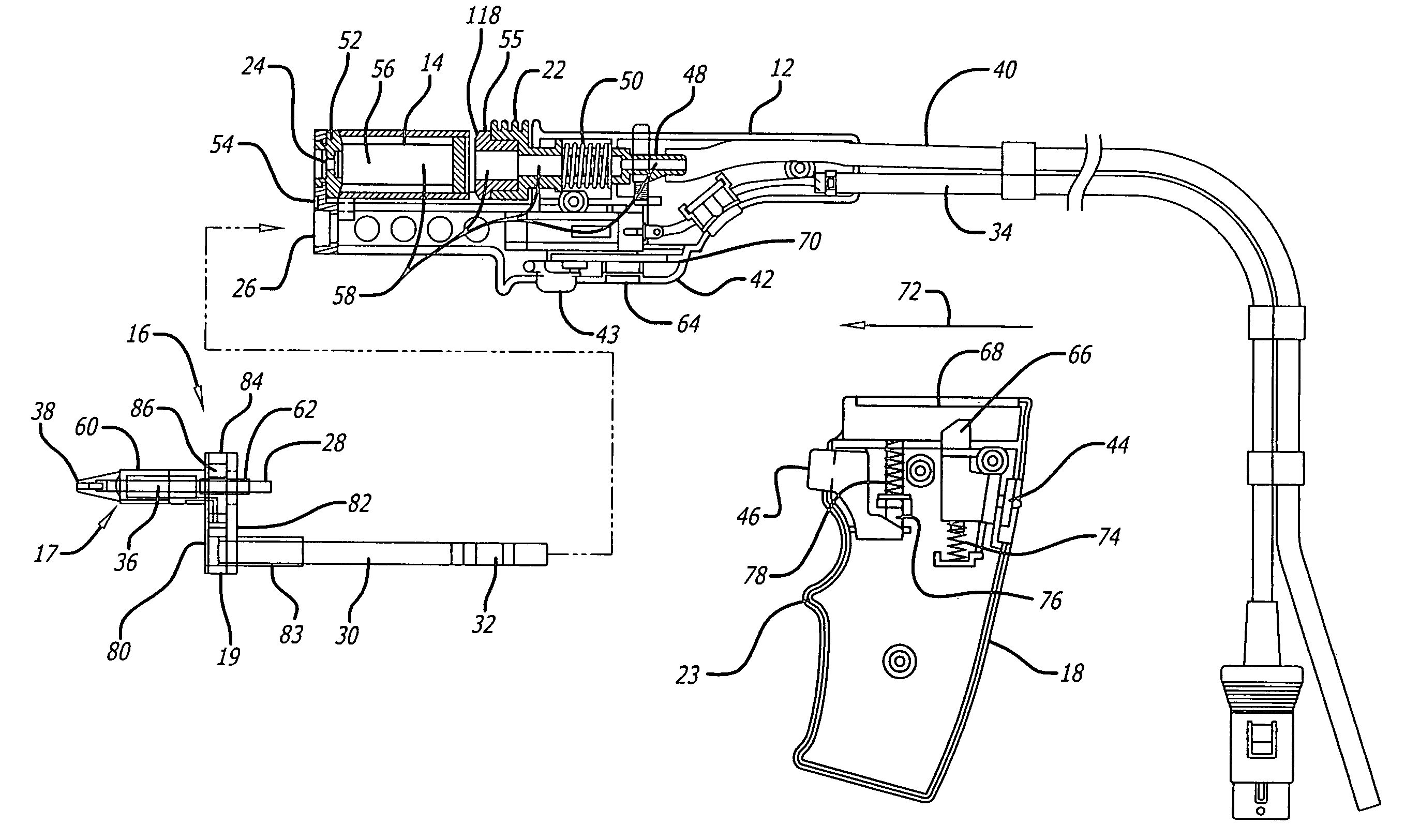
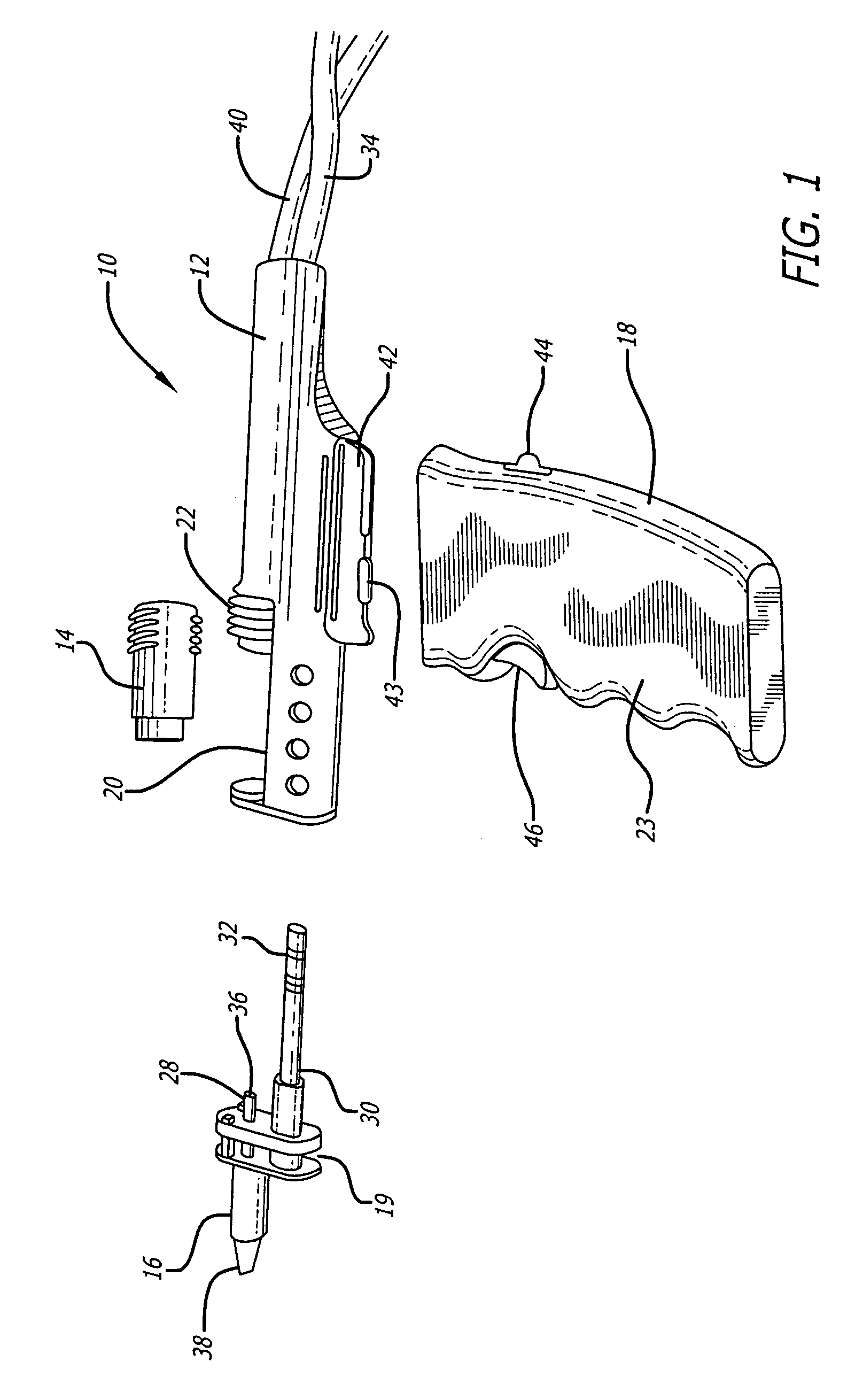
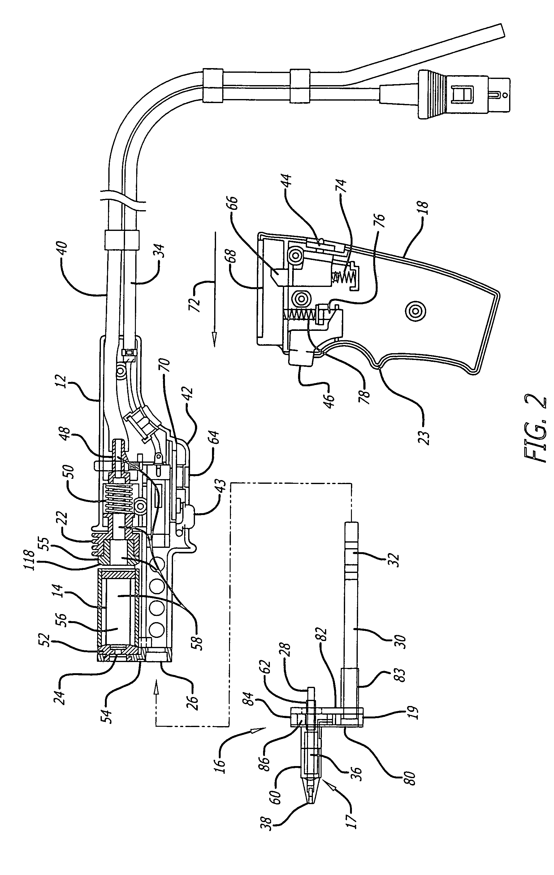
[0037]FIG. 1 illustrates a heating system show generally at 10 including a first handle 12 adapted to releaseably couple to a storage 14, a heater cartridge 16, and a second handle 18. The first handle 12 has a cavity 20 that may be formed near the heater cartridge 16. To engage the storage 14 within the cavity 20, the first handle 12 may have a back holder 22 that may move between a first position and a second position. In the first position, the length of the cavity 20 may be longer than the length of the storage 14 along the longitudinal direction of the first handle 12; whereas in the second position, the length of the cavity 20 may be similar or slightly less than the length of the storage 14. As such, when the back holder 22 is in the first position, the storage 14 may be inserted or removed from the cavity 20. To engage the storage 14 within the cavity 20, the back holder 22 may be moved from the first position to the second position so that the storage 14 may be held within ...


PUM

PropertyMeasurementUnit
meltingaaaaaaaaaa
longitudinal lengthaaaaaaaaaa
lengthaaaaaaaaaa

Abstract

This invention provides a system capable of melting solder and removing the melted solder from a substrate. The heating system includes a desoldering tool having at least two handles, a first handle and a second handle. This way, an operator may grip the first handle or the second handle depending on the operator's preference of gripping the desoldering tool. The first handle has a cavity adapted to releaseably receive a storage where the melted solder can be deposited and stored. The storage may have a divot adapted to receive a key from the first handle so that the storage may be orientated in a predetermined position relative to the cavity. The cavity in the first handle is exposed so that the storage can be readily inserted or replaced. This allows the operator to easily replace and maintain the desoldering tool without a significant downtime. The first handle is adapted to receive a heater cartridge having a transition section to couple the leading section and the electrical cartridge in a staggered manner. This configuration allows the leading section to have a shortened channel that is substantially straight and aligned with the passage formed within the first handle to minimize the resistant to flow of the melted solder through the channel which is then deposited into the storage.

Description

BACKGROUND OF THE INVENTION[0001]1. Field of the Invention[0002]This invention is directed to a heating system for removing solder from a substrate such as a circuit board. In particular, the heating system is directed to a desoldering tool that provides a tip for melting solder and retrieving the melted solder to a replaceable storage for retaining the solder and providing operators with different options in gripping the desoldering tool.[0003]2. General Background and State of the Art[0004]Desoldering tools provide heat and vacuum source to a tip in order to melt the solder on a substrate and retrieve the melted solder through the tip. Internally, the desoldering tool has a solder collection chamber where the melted solder is deposited for temporary storage. In addition, the solder collection chamber is provided with a filter to remove the flux from the vapor that accompanies the melted solder so that filtered vapor may be vacuumed away to the vacuum source without clogging the in...

Claims


Application Information

Patent Timeline
Patent Type & Authority Patents(United States)
IPC IPC(8): B23K1/018B23K101/42H05K3/34
CPCB23K1/018
Inventor MOCHIZUKI, TOSHIKAZU
Owner HAKKO CO LTD
Why Eureka
Try Eureka