Mounting of engine onto an aircraft structure

Active Publication Date: 2008-02-05
SN DETUDE & DE CONSTR DE MOTEURS DAVIATION S N E C M A
View PDF5 Cites 33 Cited by
  • Summary
  • Abstract
  • Description
  • Claims
  • Application Information

AI Technical Summary

Benefits of technology

[0026]According to one particular embodiment, a double ball-joint function is imparted to the eccentric member by providing a ball-joint both for the trunnion pin and for the rotating disc. In this way freedom of rotation is ensured over a wide angle.
[0027]Preferably, the distant pin is also mounted in a bearing forming a ball-joint. With this embodiment, it is possible to absorb axial expansions or contractions of t

Problems solved by technology

The beams are generally fairly massive and of complex shape.
The attachment of the engines on some parts of the aircraft, for example o

Method used


Image

  • Mounting of engine onto an aircraft structure
  • Mounting of engine onto an aircraft structure
  • Mounting of engine onto an aircraft structure

Examples


first embodiment

[0044]The invention such as illustrated in the description of the first embodiment given below is applied to the aft attachment, but it could also be applied to the forward or other attachment.

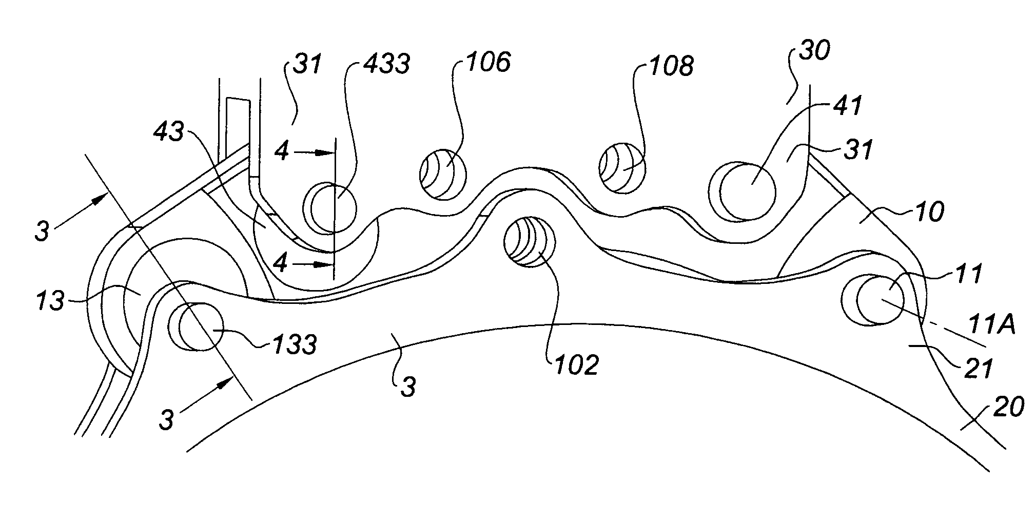
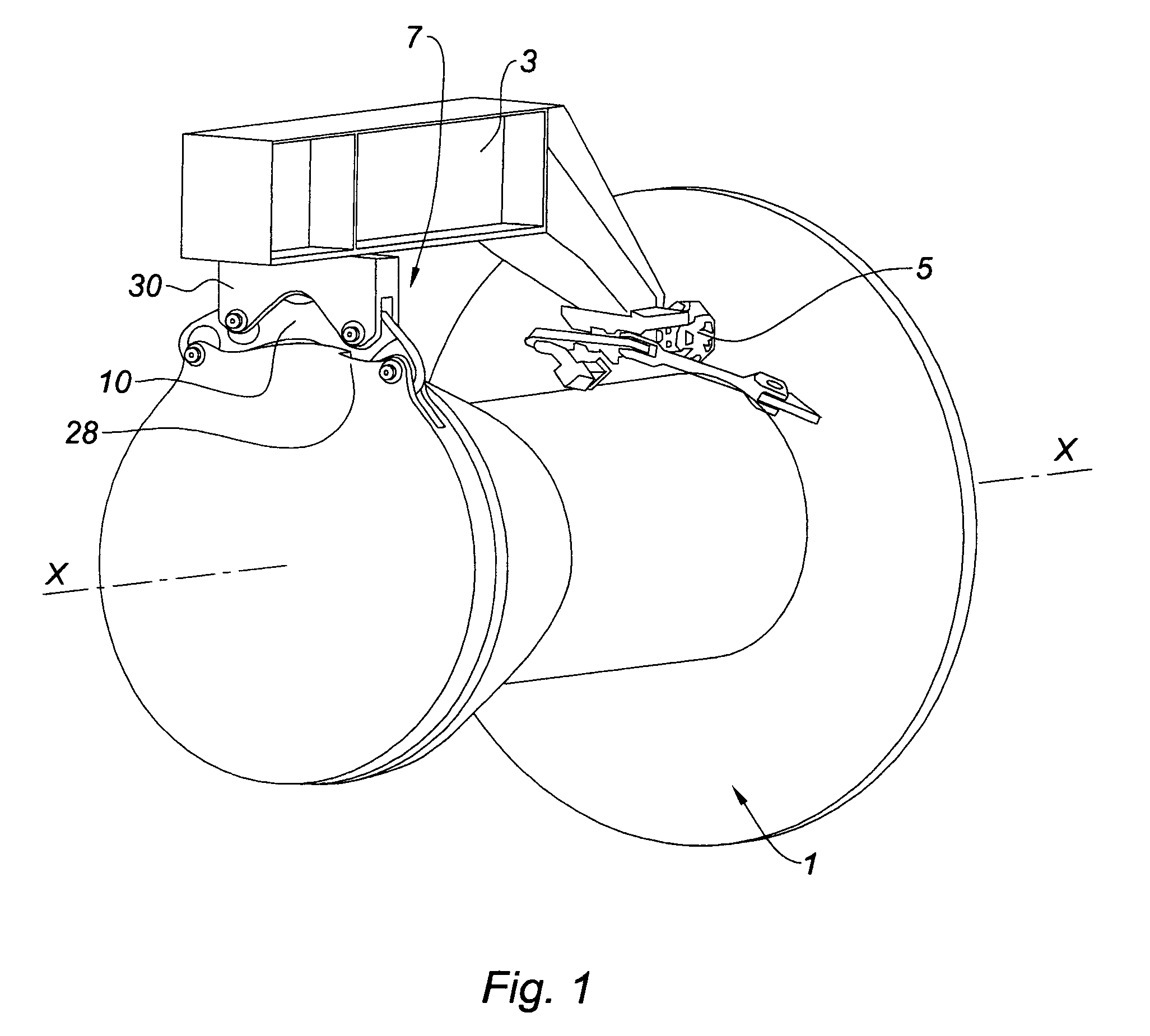
[0045]Mount 7 comprises a beam 10 positioned transverse to axis X of engine 1 between the annular frame 20, that is here integral with the turbine case, and the base 30 of the pylon.

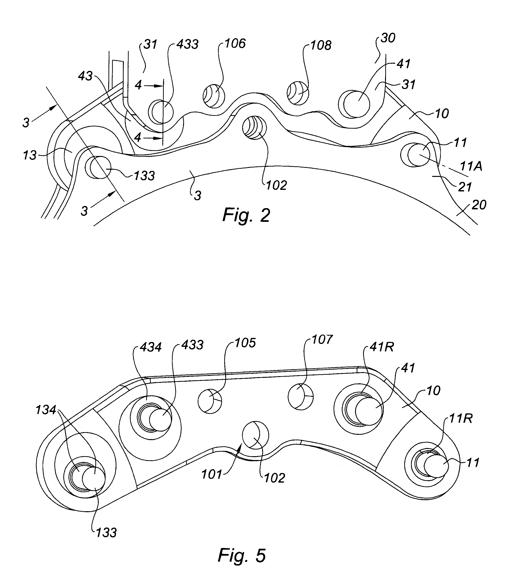
[0046]A more detailed description will now be given of the mount with reference to FIGS. 2 to 5. The beam 10 here is in the general shape of an arc of a circle with attachment means to the annular frame of case 20 which itself is in the shape of an arc of a circle and perpendicular to the engine axis. This annular frame forms two radial devises 21 and 23 spaced apart on the arc of a circle with bores and bearings to receive two trunnions or pins. The connection means of a first element such as the beam 10 to a second element such as the case 20 comprises an eccentric member 13 at one end of the beam 10 and a pin 11...

second embodiment

[0066]A second embodiment is now described of a mount incorporating eccentric members.

[0067]This concerns the forward mount of a turbofan jet engine for example. As can be seen in FIGS. 7, 8 and 9 an intermediate cross piece in the form of a beam or hanger 1010 is made integral with the aircraft structure, a pylon for example that is not shown, using appropriate attachment means. This first element 1010 is joined to a second element 1003, the intermediate case for example, by a connection means that here consists of an eccentric member 1013 at each end. The member 1013 is mounted on one side on element 1010 and on the other side on element 1003 via a trunnion which is not shown for reasons of figure clarity. The trunnion is mounted on the branches of a clevis 1023 that is part of the case.

[0068]The eccentric member comprises a disc 1131 of axis 1131A swivel-mounted in a bore of element 1010 via a bearing with spherical surface 1132 housed in a retainer 1136 that is integral with the...


PUM


Abstract

The invention pertains to an engine mount onto an aircraft structure comprising at least one connection means between a first and a second element such as an engine case and said structure, characterized by the fact that said connection means comprises an eccentric member housed in a bore of the first element, being rotational about a first axis, the eccentric member comprising a trunnion attached to the second element and of axis off-centred with respect to the first axis of rotation, the eccentric member being rotational about said off-centred axis.
The solution of the invention has the advantage of allowing a compact assembly.

Description

BACKGROUND OF THE INVENTION[0001]1. Field of the Invention[0002]The present invention relates to the mounting of jet engines onto an aircraft structure.[0003]2. Description of the Related Art[0004]A jet engine, such as a turbojet engine, may be mounted at various points of the aircraft being hung from a mast or pylon that is part of the aircraft structure. It may be mounted under the wings, attached to the fuselage, generally at the rear, or mounted in the tail unit by mounting means. The function of these mounting means is to ensure the transmission of mechanical loads between the engine and the aircraft structure. The loads to be taken into consideration are oriented along the three main directions of a reference frame related to the engine. These are the weight of the engine along the vertical axis Z, its thrust along axis X of the engine, and lateral aerodynamic loads along the transverse axis Y. The loads to be transmitted also comprise the rotational torque about the engine ax...

Claims


Application Information

Patent Timeline
IPC IPC(8): B64D27/00B64D27/26
CPCB64D27/26F16C23/10B64D2027/264B64D2027/266F16C2326/43
Inventor CHEVALIER, LYDIE MARIE HELENETESNIERE, MARC PATRICKNOIRCLERC, GABRIEL
Owner SN DETUDE & DE CONSTR DE MOTEURS DAVIATION S N E C M A
Why Eureka
Try Eureka