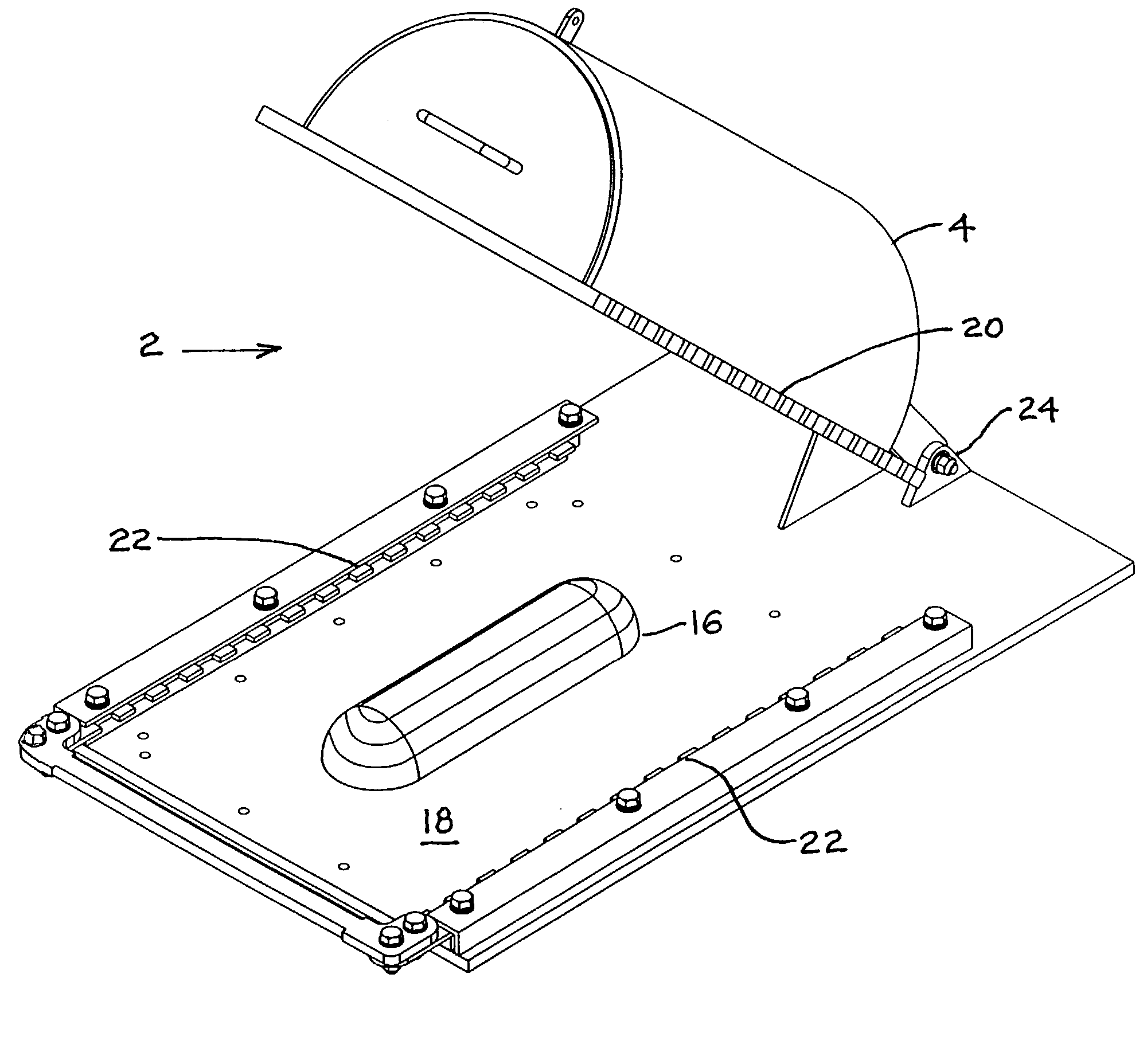
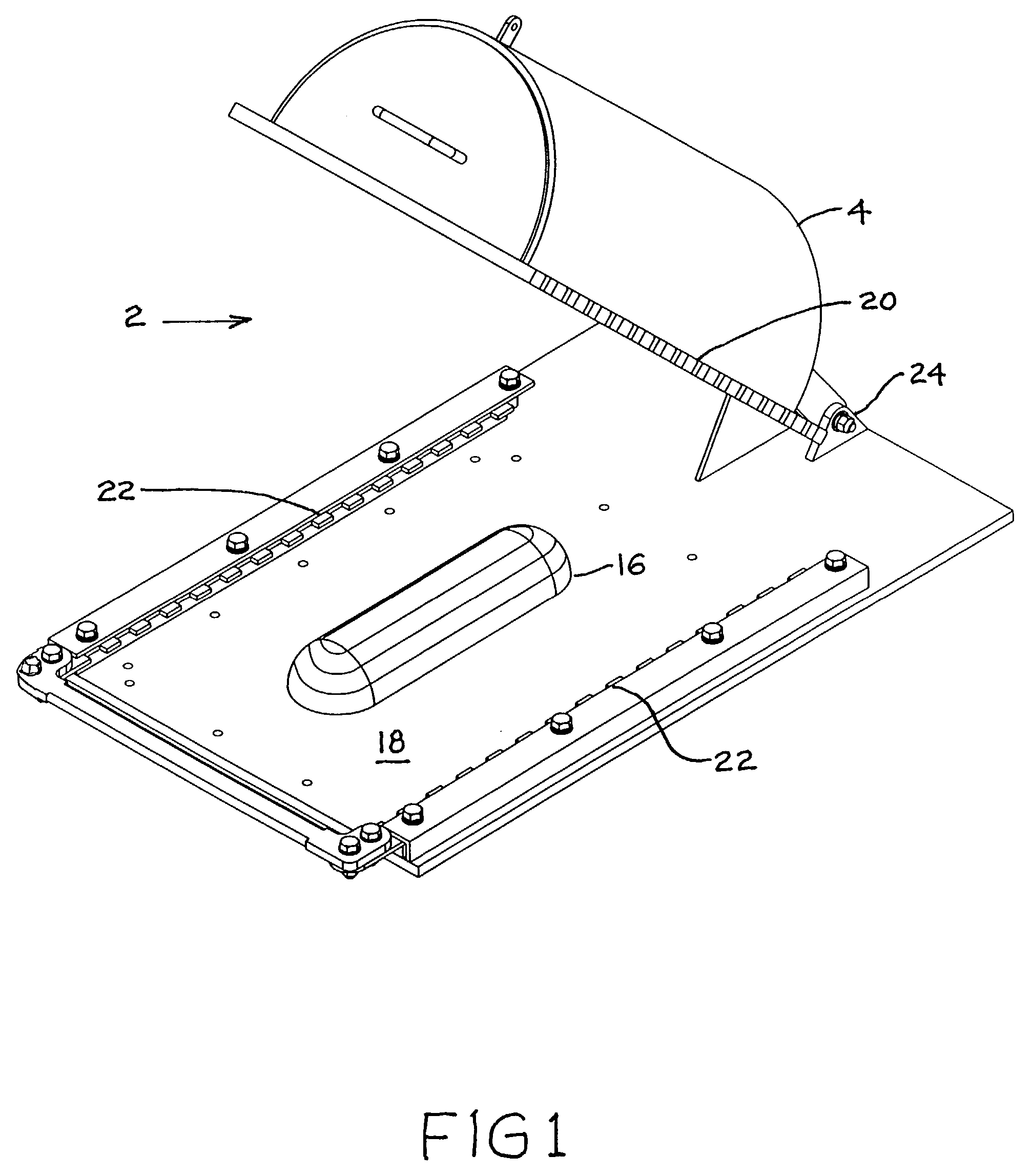
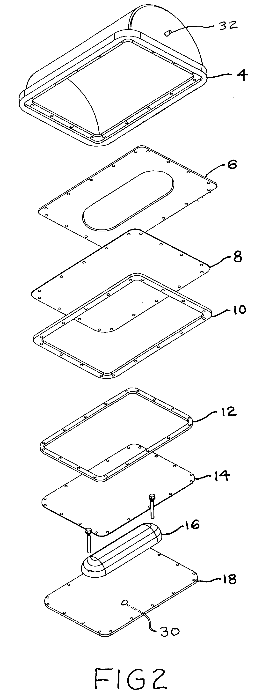
Rapid thermoform pressure forming process and apparatus

a thermoform and pressure forming technology, applied in the field of thermoform pressure forming process and apparatus, can solve the problems of high cost of materials, tooling and equipment required to make parts using pre-impregnated materials, voids between thermoform material and mold, and voids in the mold, etc., to achieve rapid heating, molding and cooling of molded parts, and superior strength and accuracy of placemen

Inactive Publication Date: 2008-02-05
ORTHO ACTIVE HLDG
View PDF22 Cites 15 Cited by
  • Summary
  • Abstract
  • Description
  • Claims
  • Application Information

AI Technical Summary

Benefits of technology

[0036]The invention is also directed to a method of fabricating thermoplastic or thermo-composite parts made with (1) rapid fabricated molds using inexpensive porous mold materials; (2) rapid heating, molding and cooling of the molded parts; (3) in the case of a commingled thermo-composite product such as Twintex, rapid heating consolidation and cooling of the parts; and (4) separate heating cycles for different layers of lamination prior to consolidation in the mold apparatus. This allows for a wide variety of surface finishes and structural reinforcements to be incorporated into a part prior to molding or consolidation. Balanced loading of medium to large size molds made of inexpensive porous mold materials (MDF) is thus possible. Accurately positioned embedded fasteners can be located within the composite layup to produce a fastener of superior strength and accuracy of placement.
[0037]A method of making a knee brace or other non-invasive orthopedic product using commingled product and stretchable cosmetic material compatible with the commingled product, and clear polypropylene film, heated separately and then consolidated and cooled together. This produces a strong durable product with an attractive outer coating.

Problems solved by technology

A perennial problem with many existing thermoforming processes, particularly, when dealing with large thermoformed materials and continuous fiber reinforcements, is that voids appear between the thermoformed material and the mold.
Another problem that occurs when there are recessed areas in the mold is resin pooling in the recessed areas when dealing with pre-consolidated thermo-compositess.
A further problem is that folds and pleats in the thermoformed product occur at the corners and other areas of the thermoformed product when complex and deep concave or convex articles are formed.
However, the materials, tooling and equipment required to make parts using pre-impregnated materials are very expensive.
However, unlike conventional fiberglass products that require the saturation of the fibers with a liquid resin such as a polyester, an acrylic or a two part epoxy (commonly referred to as thermo-set fiber composites), the Twintex material requires heating to 400 degrees Fahrenheit and then either pressure or vacuum forming the part for the duration of the cooling cycle.
However, all of the methods involve either expensive tooling and equipment, long heating and cooling cycle times, or a combination of the two.

Method used


Image

  • Rapid thermoform pressure forming process and apparatus
  • Rapid thermoform pressure forming process and apparatus
  • Rapid thermoform pressure forming process and apparatus

Examples


second embodiment

[0097]FIG. 14 is an exploded isometric view of the invention comprising a double pressure chamber with triple bladder. Specifically, FIG. 14 illustrates clockwise from the bottom left flexible air pressure manifold lines 38, with control valves 39, lower pressure chamber 40, chamber connector hinge 45, hinge axis pins 47, lower bladder 42, lower flange plate 44, with an inlet / outlet 46, convex mold 48, second lower bladder 50, second lower bladder retaining frame 52, upper retaining frame 54, upper bladder 56, upper flange 58, and upper air pressure chamber 60. Chamber 40 has a connecting air inlet / outlet connector 41 which connects with the manifold 38. Likewise, chamber 60 has an inlet / outlet connector 62 which connects with manifold 38.

[0098]FIGS. 15 to 20 show a sequence of steps for molding a thermoformable composite or thermoplastic material on a positive (convex) mold surface. FIG. 15 illustrates an end view of the double pressure chamber and triple bladder second embodiment ...

third embodiment

[0109]FIG. 26 illustrates an end section view of the dual air pressure chamber, triple bladder third embodiment with the upper air pressure chamber 60 pivoted away from the lower air pressure chamber 40, with the negative molded thermoformable fibre reinforced material 64 lifted up off the second lower bladder 50 above the mold, including flash 72 and trim line 71 around the thermoformed part 64. The part is now ready for trimming. A concave molded thermoformable fibre reinforced composite material 64 is formed.

fourth embodiment

[0110]FIG. 27 illustrates an exploded end section view of the invention wherein an embedded fastener attachment 76 is accurately located between two or more layers of thermoformable fibre reinforced composite material 78, 80 over a mold 82. A jig (not shown) or some other location device can be used to position the attachment accurately on the mold prior to heating and pressurizing the thermo-composite material.

[0111]FIG. 28 illustrates an end section view of the fourth embodiment of the invention wherein the embedded fastener attachment 76 is encased between the two layers of thermoformable fibre reinforced composite material 78, 80 over the mold 82. The two layers 78, 80 are heated and then compressed together utilizing any of the three thermoforming methods illustrated in FIGS. 1 to 26. A bolt 84 is installed, using the rapid molding process as illustrated in previous drawings and according to the description. Embedded fasteners can be post machined to receive standard sized bolt...


PUM

PropertyMeasurementUnit
temperatureaaaaaaaaaa
timeaaaaaaaaaa
air pressureaaaaaaaaaa

Abstract

This invention relates to a novel apparatus and process for producing thermoplastic articles. In one aspect, the invention pertains to a process for manufacturing fiberglass products using a fiberglass material consisting of fiberglass strands commingled with heat-formable polypropylene strands. A molding apparatus comprising: (a) an air pressure chamber with an open side; (b) a flange plate fitted to the open side of the air pressure chamber, said flange plate having an opening therein for receiving a mold; (c) an upper bladder associated with the flange plate and covering the opening; (d) a base pressure plate; (e) a mold positioned on the base pressure plate; and (f) a locking mechanism for securing the air pressure chamber with the base pressure plate, and balanced air pressure in each chamber during molding.

Description

FIELD OF THE INVENTION[0001]This invention relates to a novel apparatus and process for producing thermoplastic articles. In one aspect, the invention pertains to a process for manufacturing fiberglass products using a fiberglass material consisting of fiberglass strands commingled with heat-formable polypropylene strands.BACKGROUND OF THE INVENTION[0002]There are many existing processes for forming thermoplastic (thermoforming) articles including vacuum molding, injection molding, extrusion molding and the like. A perennial problem with many existing thermoforming processes, particularly, when dealing with large thermoformed materials and continuous fiber reinforcements, is that voids appear between the thermoformed material and the mold. Another problem that occurs when there are recessed areas in the mold is resin pooling in the recessed areas when dealing with pre-consolidated thermo-compositess. A further problem is that folds and pleats in the thermoformed product occur at the...

Claims


Application Information

Patent Timeline
Patent Type & Authority Patents(United States)
IPC IPC(8): B29C51/10B29C51/28B29B15/10B29C43/36B29C70/44B29C70/46
CPCB29C43/10B29C43/3642B29C70/44B29C70/465B29C33/20B29C2043/3649B29K2105/0872B29L2031/3041
Inventor KIRCHNER, GRANT DAVID
Owner ORTHO ACTIVE HLDG
Why Eureka
Try Eureka