
Linear actuator comprising velocity sensor

a technology of velocity sensor and linear actuator, which is applied in the direction of motor/generator/converter stopper, magnetic body, dynamo-electric converter control, etc., can solve the problems of difficult to achieve force consistency, general non-programmable thrust force, and limited reliability and lifespan, so as to achieve effective and cost-effective

Active Publication Date: 2008-02-05
ASM TECH SINGAPORE PTE LTD
View PDF6 Cites 15 Cited by
  • Summary
  • Abstract
  • Description
  • Claims
  • Application Information

AI Technical Summary

Benefits of technology

The invention is a new type of linear actuator that solves some of the problems of previous systems. It uses a magnetic field and two coils to detect and control the movement of an actuation arm. The second coil also produces a voltage that indicates its speed, which is used by a controller to adjust the current flow in the first coil and drive the arm. This new system is more efficient and cost-effective, and can detect and prevent jams.

Problems solved by technology

Jam detection is important because semiconductor substrates are generally fragile and vulnerable, and excessive external forces acting on their components during a jam can result in damage.
There are certain drawbacks in this conventional design.
Since it adopts a traction drive mechanism, its reliability and lifespan are limited by premature wear.
Also, the thrust force is generally non-programmable and uncontrollable for different types of leadframes.
Even with stringent control over manufacturing tolerance and assembly, force consistency is difficult to achieve for the above reason.
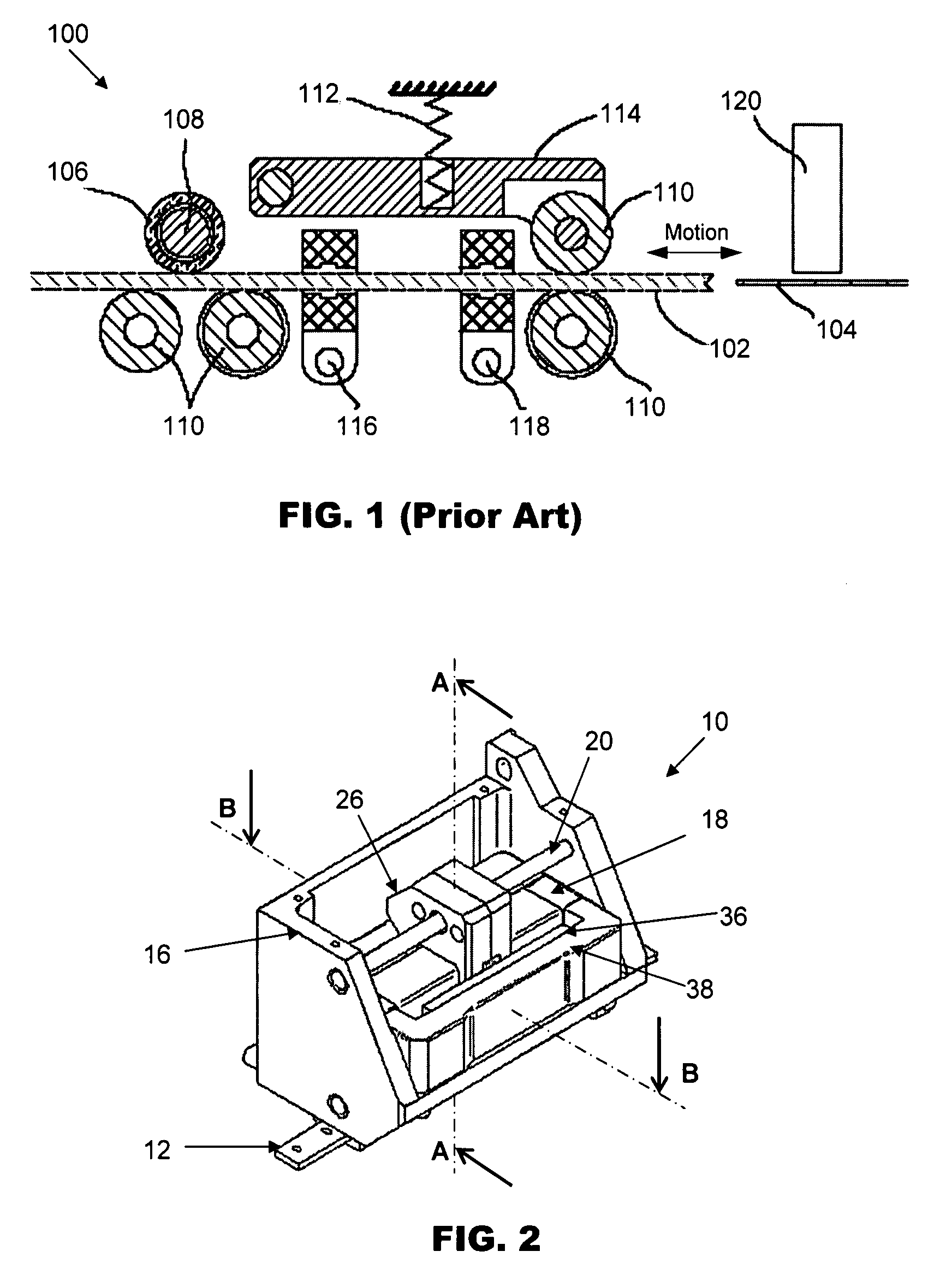
Especially for thick leadframes, the deformation in the leadframes may be small, making it very difficult to sense deformations in the leadframes if they are jammed.
Finally, this jam sensing module entails significant additional cost, which is likely to be even higher than the cost of the ejector system itself.

Method used


Image

  • Linear actuator comprising velocity sensor
  • Linear actuator comprising velocity sensor
  • Linear actuator comprising velocity sensor

Examples


Embodiment Construction

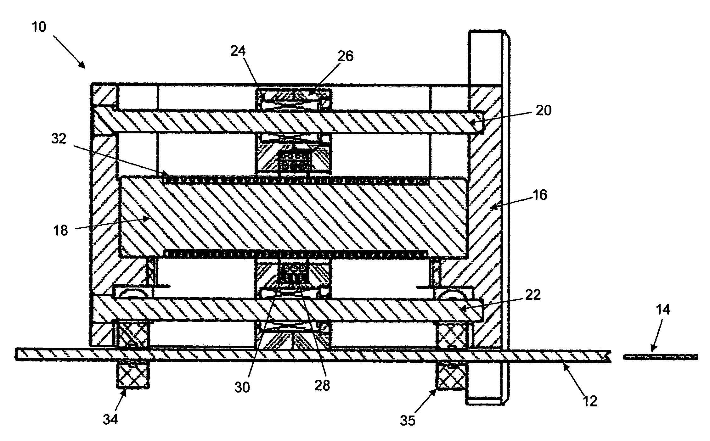
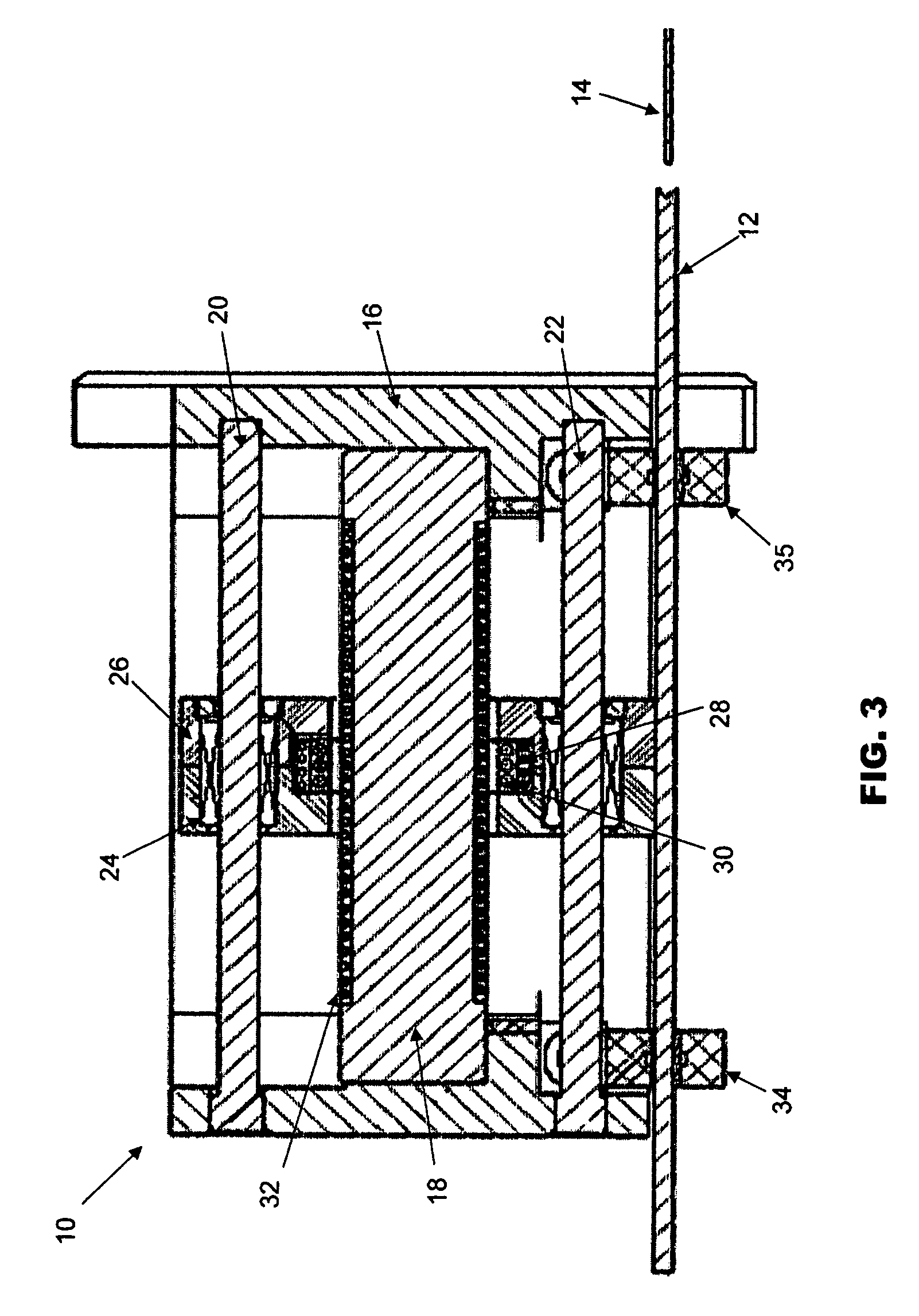
[0017]The preferred embodiment of the present invention will be described with reference to FIGS. 2 and 3 in relation to an ejector system, although it should be appreciated that the invention is also applicable to other actuation systems. FIG. 2 is an isometric view of an ejector system 10 comprising a linear actuator in accordance with the preferred embodiment of the invention. FIG. 3 is a schematic cross-sectional side view of the ejector system looking along sectional line A-A of FIG. 2.

[0018]The ejector system 10 includes an actuation arm in the form of an ejector arm 12 for pushing an object, such as a leadframe 14. The ejector arm 12 is mounted onto a housing 16 and is configured to be slidable with respect thereto. The housing 16 houses components for driving the ejector arm 12 and for sensing a velocity at which the ejector arm 12 is driven.

[0019]The main component for driving the ejector arm 12 consists of a voice coil motor (VCM), which comprises a first coil, such as a m...


PUM


Abstract

A linear actuator for a motion system is provided with a velocity sensor for monitoring a velocity of an actuation arm that it is driving. The linear actuator comprises a magnetic field, a first coil that is controllably movable within the magnetic field by adjusting a current flowing through the first coil whereby to drive the actuation arm and a second coil that is movable with the first coil and configured such that a voltage is inducible in the second coil that is proportional to its velocity. A controller device is connected to the second coil for receiving feedback indicating the voltage induced in the second coil whereby a velocity of the actuation arm is determinable, wherein the controller device is further connected to the first coil and is operative to adjust the current flowing in the first coil based upon said feedback for controllably driving the actuation arm.

Description

FIELD OF THE INVENTION[0001]The invention relates to a linear actuator of a motion system for driving an actuation arm, and in particular to a linear actuator that is fitted with a velocity sensor For monitoring the velocity of the actuation arm that is being driven.BACKGROUND AND PRIOR ART[0002]Ejector systems are used in the semiconductor industry for a variety of purposes. One use is in the area of automatically transferring a semiconductor substrate onto a work-holder for processing. For example, such an ejector system is used to automatically transfer substrates from their containers to wire bonding machines that make wire connections between electronic components attached on the substrate and electrical connection pads on the substrate.[0003]More specifically, in a typical wire bonding machine, an ejector system is used to eject substrates (commonly in the form of leadframes) from a magazine onto a work-holder channel. The substrates are pushed one at a time onto the work-hold...

Claims


Application Information

Patent Timeline
Patent Type & Authority Patents(United States)
IPC IPC(8): H02K41/00H02K7/00
CPCH01F7/066H01F7/1844H01L21/67121H02K41/0356H01L2924/0002H01L2924/00H04B1/385H03G3/3042H04B2001/3855
Inventor NG, HON YU PETERLIAO, YOU YONGWIDDOWSON, GARY PETERGAUNEKAR, AJIT
Owner ASM TECH SINGAPORE PTE LTD
Learn More