Plate member, magnetic element using the same, and magnetic element manufacturing method

a technology of magnetic elements and manufacturing methods, applied in the field of magnetic elements, can solve the problems of increasing the production cost of magnetic elements, and achieve the effects of reducing the manufacturing cost of molds, reducing the number of windings of coils, and facilitating the property change of magnetic elements

Active Publication Date: 2008-02-05
SUMIDA CORP
View PDF4 Cites 14 Cited by
  • Summary
  • Abstract
  • Description
  • Claims
  • Application Information

AI Technical Summary

Benefits of technology

[0015]Therefore, it is not required to fabricate various plate members in accordance with the joint positions of the ends of the coil for each winding number of coil. With this, it is not required to fabricate the molds for pressing corresponding to the shapes of the plate members, so that the mold fabrication cost can be reduced. Further, with the use of the plate member according to the present invention, the winding number of the coil can be adjusted easily, so that the property change of the magnetic element can be made easily.
[0017]When it is configured as in the above described manner, it is easily possible to connect the one end and the other end of the coil which have different heights each other in the normal direction to the inner terminal portions positioning at different heights easily.
[0020]When it is configured as in the above described manner, out of the plural terminal joint portions provided in the winding number adjustment means, those terminal joint portions having positional relationships corresponding to the ends in accordance with the winding number of coil are jointed. The winding number adjustment means is included inside the core. With this, it is not required to fabricate the plate members of various shapes in accordance with the joint positions of the ends of the coil. Therefore, it is not required to fabricate the molds for pressing corresponding to the shapes of the plate members, so that the mold fabrication cost can be reduced. Further, the winding number of coil can be changed easily, and the property change of the magnetic element can be made easily as well.
[0022]When it is configured as in the above described manner, the ends of the coil facing each other are jointed with the inner terminal portions at the sides of the ends that do not face each other, respectively, while the end and the inner terminal portion are in the state of being overlapped each other. Therefore, the inner terminal portion is disposed so as not to protrude toward a not-facing side, so that the thickness of the magnetic element can be reduced while ensuring the winding number of the coil. Further, when such a jointing method is adopted, when the magnetic elements have the same height, the magnetic element according to the present invention can have a larger inductance value as compared to the conventional magnetic element. Similarly, the magnetic elements have the same height as well as the same winding number of the coil, the magnetic element according to the present invention allows a higher winding wire as compared to the conventional magnetic elements. Backed by this, the cross-section of the winding wire can be increased, so that the impedance of the magnetic element can be reduced.
[0023]Further, the higher the density of the core is, the above-described inductance value increases, however, when the above-described joint method is adopted and the magnetic elements are allowed to have the same height and inductance value, it is possible to reduce the pressing pressure at the press molding as compared to the conventional magnetic elements. Backed by this, the operation life of the mold used in the press molding can be extended. In addition, since the pressing pressure can be reduced, the broken ratio of an insulating layer existing at the periphery of the particles composing the core due to the pressing pressure can be reduced. Backed by this, since the pressing pressure can be reduced, it is possible to reduce the ratio of the insulating layer that is at the periphery of the particles composing the core and broken by the pressure. With this, an insulation resistance in the magnetic element can be increased.
[0026]The magnetic element formed through such respective steps does not require the plate members of various shapes in accordance with the joint positions or the like of the ends of the coil. With this, it is not required to fabricate the molds for pressing in accordance with the shapes of the plate members, so that the mold fabrication cost can be reduced. Further, the winding number of the coil can be adjusted easily, and the property change of the magnetic element can be made easily as well.

Problems solved by technology

However, the change of the mold to form the plate member for each case in response to each customer request increases the production cost of the magnetic elements, being a problem.

Method used


Image

  • Plate member, magnetic element using the same, and magnetic element manufacturing method
  • Plate member, magnetic element using the same, and magnetic element manufacturing method
  • Plate member, magnetic element using the same, and magnetic element manufacturing method

Examples


Embodiment Construction

)

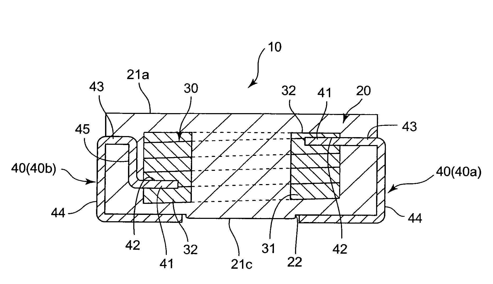
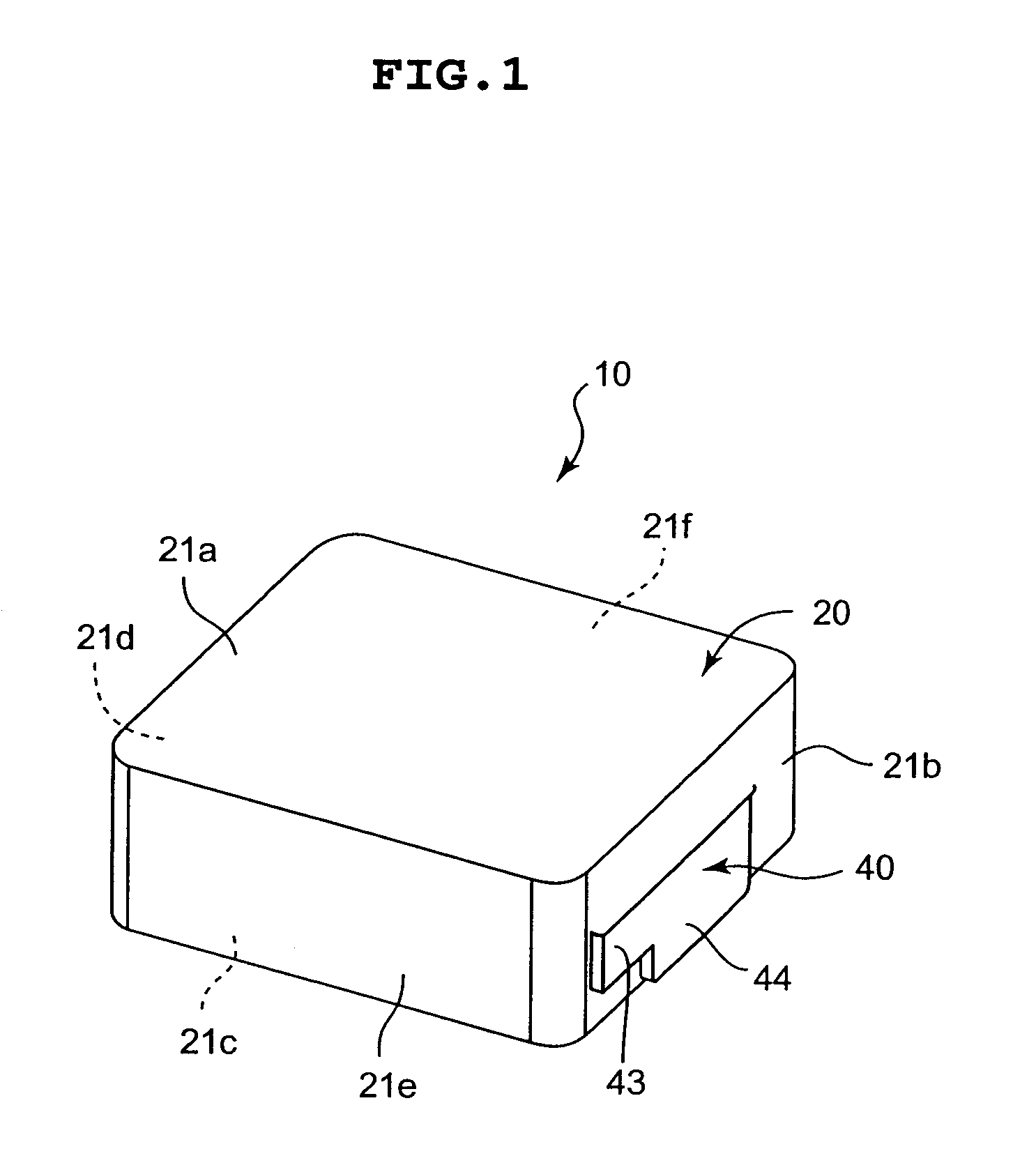
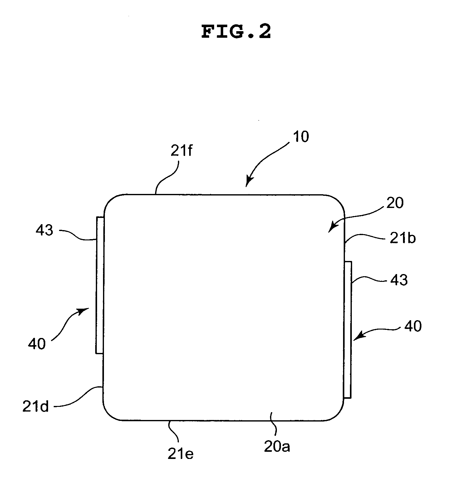
[0037]Hereinafter, a description will be given of a magnetic element 10 according to an embodiment of the present invention based on FIGS. 1 to 10. FIG. 1 is a perspective view showing an entire configuration of the magnetic element 10. FIG. 2 is a plan view showing a state of the magnetic element 10 viewing from the above (an upper surface 21a). FIG. 3 is a bottom view showing the state of the magnetic element 10 viewing from a bottom surface (a lower surface 21c). FIG. 4 is a front view showing the state of the magnetic element 10 viewing from the front. Further, FIG. 5 is a sectional side view taken along an A-A line in FIG. 3 and showing a configuration of the magnetic element 10.

[0038]Note that, in the description below, of the magnetic element 10, an upper side indicates the upper surface 21a side being distant from the later-described lower surface 21c, and a lower side indicates the side on which later described recessed portions 22 for terminal are provided. Also, a height...


PUM

PropertyMeasurementUnit
inductanceaaaaaaaaaa

Abstract

A plate member includes a frame portion (51) provided in a state of coupling both one end portion and other end portion and mounting terminal portions (44) protruding from the one end portion and the other end portion of said frame portion (51) to approach each other, from which a PCB joint portions (46) to be a mounting portion to a PCB are formed by cutting and bending when manufacturing a magnetic element. Further, a winding number adjustment means (41), which is capable of selecting joint portions with ends of a coil and adjusting the winding number of the coil in accordance with the selection, protrudes from the one end portion and the other end portion to approach each other farther as compared to the mounting terminal portions (44).

Description

CROSS-REFERENCES TO RELATED APPLICATIONS[0001]This application claims priority to Japanese Application No. 2004-332302 filed Nov. 16, 2004 and Japanese Application No. 2005-268629 filed Sep. 15, 2005, the entire disclosures of which are hereby incorporated by reference.BACKGROUND OF THE INVENTION[0002]1. Field of the Invention[0003]The present invention relates to a magnetic element used for various electric products such as a power supply section of a computer, and particularly to a plate member to form the magnetic element, the magnetic element using the plate member, and a manufacturing method of the magnetic element.[0004]2. Description of the Related Art[0005]Among magnetic elements such as an inductor, there exists one formed by press-molding and subsequently thermosetting a paste being a mixture of magnetic powders, resin, and the like. The magnetic element of such a type is formed to have the same shape as of a hollow section (cavity) formed by facing a core and a drag to ea...

Claims


Application Information

Patent Timeline
Patent Type & Authority Patents(United States)
IPC IPC(8): H01F27/29H01F27/02
CPCH01F27/027H01F27/292Y10T29/49032H01F27/2847H01F41/005H01F2017/046Y10T29/49146Y10T29/49021Y10T29/49071Y10T29/4922Y10T29/49222Y10T29/49073Y10T29/49171Y10T29/4905H01F27/255H01F27/30H01F17/045H01F41/06
Inventor SANO, KANYAMADA, SATORU
Owner SUMIDA CORP
Why Eureka
Try Eureka