Eureka AIR delivers breakthrough ideas for toughest innovation challenges, trusted by R&D personnel around the world.

Liquid-crystal driving circuit and method

a driving circuit and liquid crystal technology, applied in the direction of static indicating devices, television systems, instruments, etc., can solve the problems of inability to respond to rapidly changing moving pictures, inability to accurately control the and increase the necessary memory size, so as to reduce the capacity of frame memory, avoid inaccuracy, and the effect of accurately controlling the response speed of liquid crystals

Inactive Publication Date: 2008-02-05
TRIVALE TECH
View PDF16 Cites 18 Cited by
  • Summary
  • Abstract
  • Description
  • Claims
  • Application Information

AI Technical Summary

Benefits of technology

[0013]The present invention addresses the problem above, with the object of providing a liquid-crystal driving circuit and liquid-crystal driving method capable of accurately controlling the response speed of the liquid crystal in a liquid-crystal display device by appropriately controlling the voltage applied to the liquid crystal.
[0014]Another object is to provide a liquid-crystal driving circuit and liquid-crystal driving method capable of accurately controlling the voltage applied to the liquid crystal, even if the capacity of the frame memory for reading the image one frame before is reduced.

Problems solved by technology

Liquid crystals have the drawback of being unable to respond to rapidly changing moving pictures, because their transmissivity changes according to a cumulative response effect.
A problem in the image display device shown in FIG. 72 is that as the number of pixels displayed by the liquid-crystal panel 104 increases, so does the amount of image data written into the image memory 101 for one frame, so the necessary memory size increases.
Therefore, when the gray level changes only slightly, an overly high voltage is applied to the liquid crystal, causing a degradation of image quality.
Thus when decimation is carried out, the voltages for the pixels with decimated pixel data are not controlled accurately, and the image quality is degraded by the application of unnecessary voltages.

Method used


Image

  • Liquid-crystal driving circuit and method
  • Liquid-crystal driving circuit and method
  • Liquid-crystal driving circuit and method

Examples


first embodiment

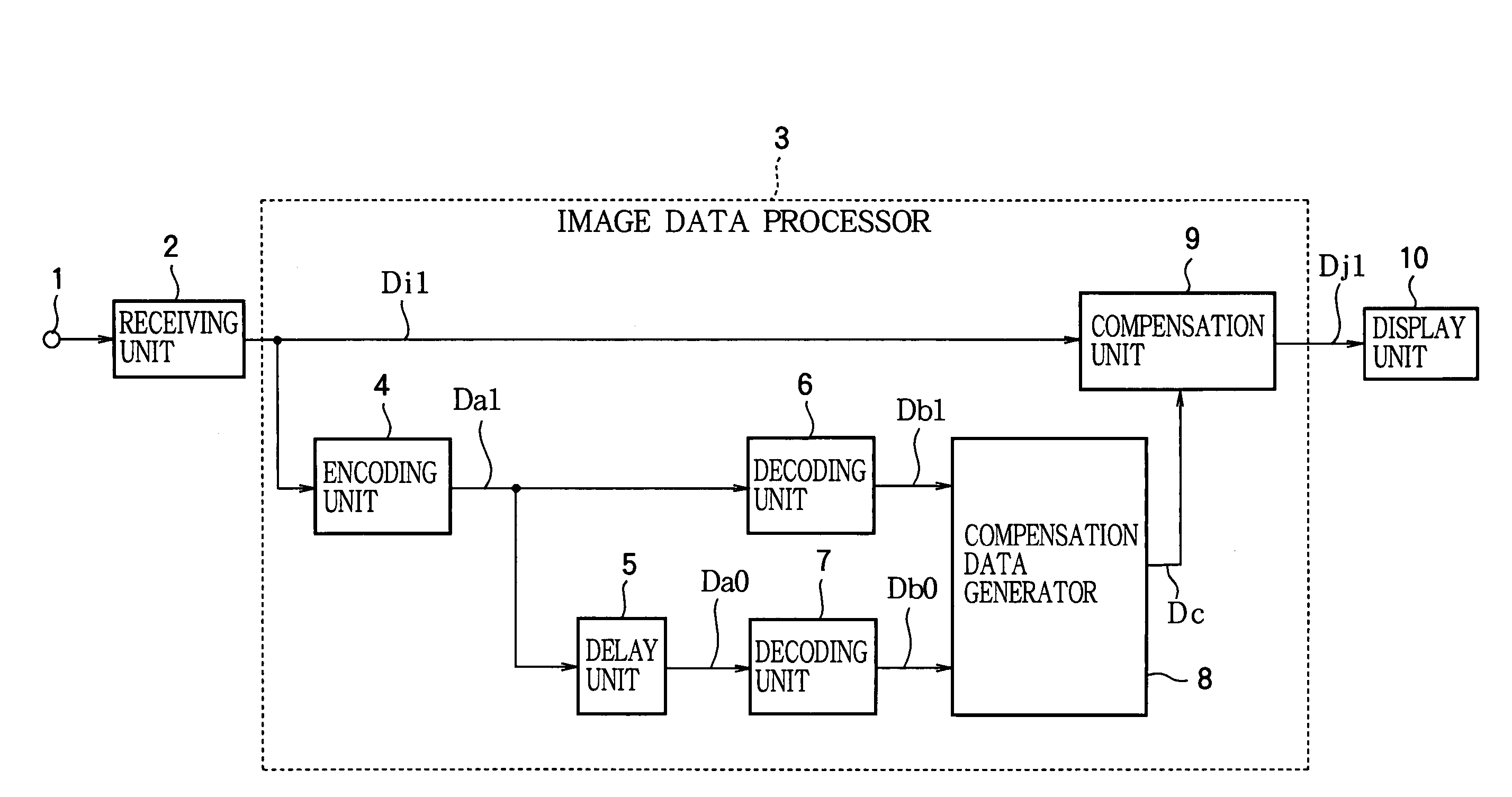
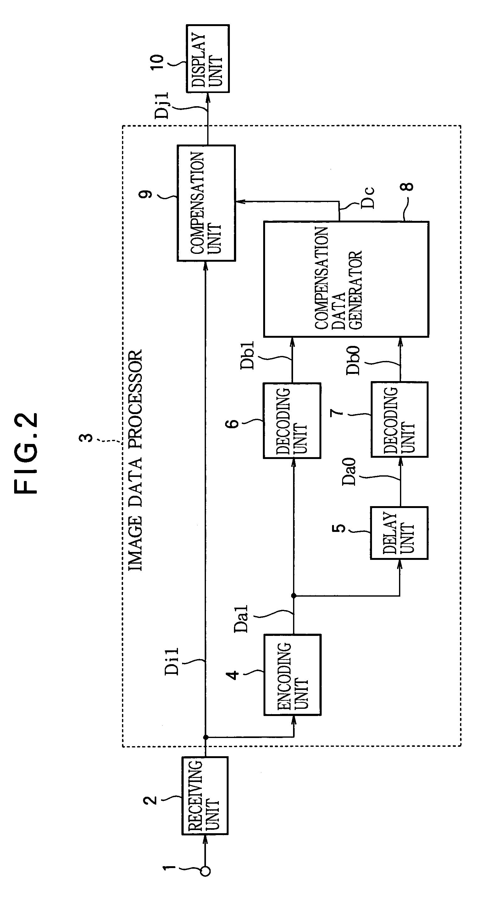
[0188]FIG. 2 is a block diagram showing the structure of a liquid-crystal driving circuit according to the invention. A receiving unit 2 receives a picture signal through an input terminal 1, and sequentially outputs present image data Di1 representing one image frame (referred to below as the present image). An image data processor 3 comprising an encoding unit 4, a delay unit 5, decoding units 6, 7, a compensation data generator 8, and a compensation unit 9 generates new image data Dj1 corresponding to the present image data Di1. A display unit 10 comprising a generally used type of liquid-crystal display panel performs the display operation by applying voltages corresponding to gray-scale values in the image to a liquid crystal.

[0189]The encoding unit 4 encodes the present image data Di1 and outputs encoded data Da1. Block truncation coding methods such as FBTC or GBTC can be used to encode the present image data Di1. Any still-picture encoding method can also be used, including ...

second embodiment

[0214]FIG. 13 shows a first structure of the compensation data generator 8 according to the invention. A data conversion unit 12 converts the number of bits with which decoded image data Db1 are quantized, by reducing the number from eight bits to three bits, for example, and outputs new decoded image data De1 corresponding to the decoded image data Db1. A lookup table 13 outputs the compensation data Dc1 according to decoded image data Db0 and the decoded image data De1 with the converted number of bits.

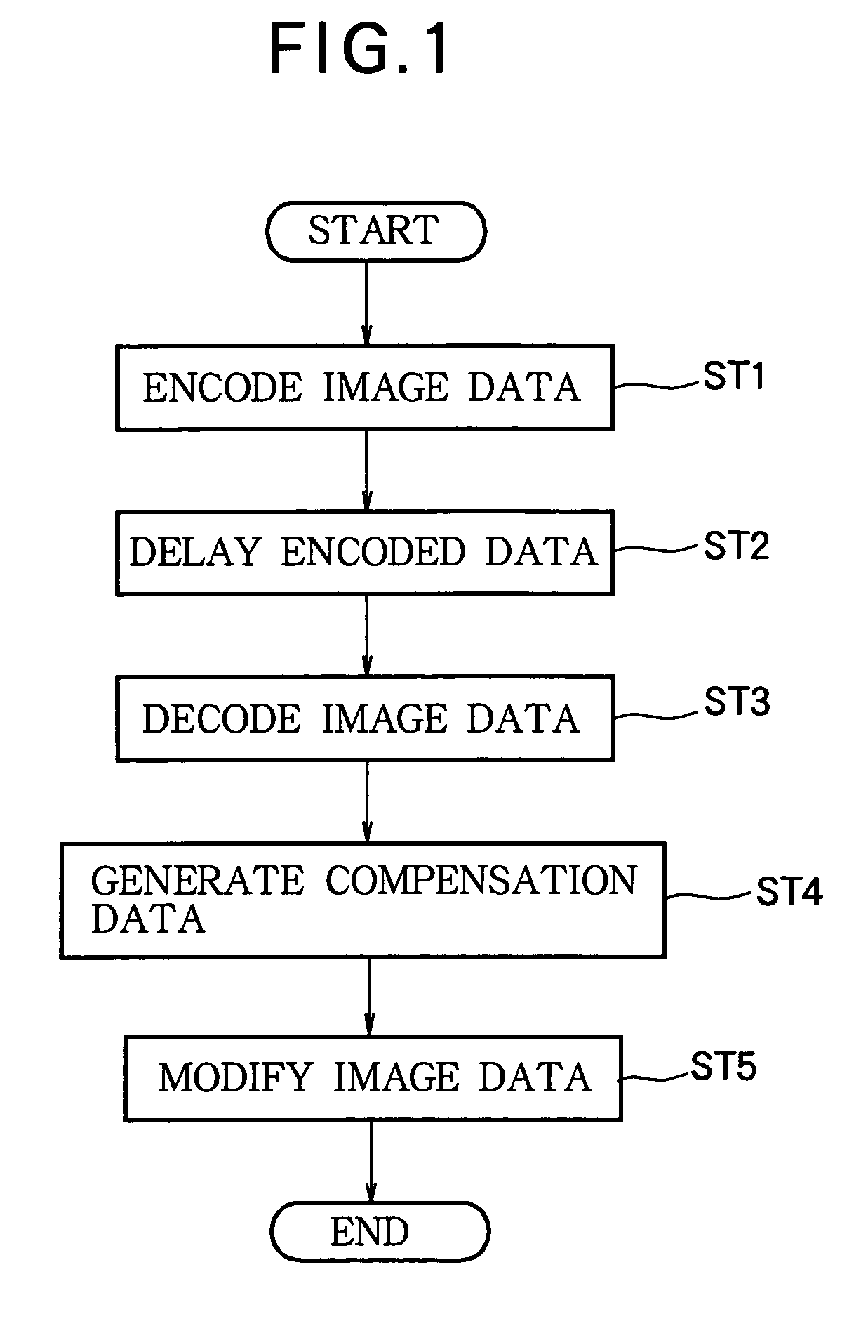
[0215]FIG. 12 is a flowchart showing the operation of a liquid-crystal driving circuit having the compensation data generator 8 shown in FIG. 13. In the decoded data conversion step (St6), the number of bits with which the decoded image data Db1 are quantized is reduced by the data conversion unit 12. In the following compensation data generation step (St4), the compensation data Dc1 are output from the lookup table 13 according to decoded image data Db0 and the decoded image data D...

third embodiment

[0230]FIG. 23 shows a first structure of the compensation data generator 8 according to the invention. A data conversion unit 17 quantizes decoded image data Db1 by a linear quantization method, converting the number of bits from eight to three, for example, and outputs new decoded image data De1 with the converted number of bits. At the same time, the data conversion unit 17 calculates an interpolation coefficient k1 described below. A lookup table 18 outputs two internal compensation data values Df1 and Df2 according to the three-bit decoded image data De1 with the converted number of bits and the eight-bit decoded image data Db0. A compensation data interpolation unit 19 generates compensation data Dc1 according to these two compensation data values Df1 and Df2 and the interpolation coefficient k1.

[0231]FIG. 22 is a flowchart showing the operation of a liquid-crystal driving circuit having the compensation data generator 8 according to the embodiment in FIG. 23. In the decoded da...


PUM

PropertyMeasurementUnit
voltagesaaaaaaaaaa
frequencyaaaaaaaaaa
grayscaleaaaaaaaaaa

Abstract

A liquid-crystal driving circuit has an image data processor that, for example, encodes the present image, decodes the encoded image, delays the encoded image by one frame interval, decodes the delayed encoded image, and uses the two decoded images to generate compensation data for adjusting the gray-scale values in the present image. The encoding process reduces the amount of image data, thereby reducing the size of the frame memory needed to delay the image. The compensation data preferably cause the liquid crystal to reach transmissivity values corresponding to the gray-scale values of the present image within substantially one frame interval. This enables the response speed of the liquid crystal to be controlled accurately.

Description

[0001]This application is a Divisional of application Ser. No. 10 / 234,192, filed on Sep. 5, 2002, now U.S. Pat. No. 6,756,955 the entire contents of which are hereby incorporated by reference and for which priority is claimed under 35 U.S.C. § 120.BACKGROUND OF THE INVENTION[0002]1. Field of the Invention[0003]The present invention relates to a liquid-crystal display device employing a liquid-crystal panel and, more particularly, to a liquid-crystal driving circuit and liquid-crystal driving method for improving the response speed of the liquid crystal.[0004]2. Description of the Related Art[0005]Liquid crystals have the drawback of being unable to respond to rapidly changing moving pictures, because their transmissivity changes according to a cumulative response effect. One method of solving this problem is to improve the response speed of the liquid crystal by increasing the liquid-crystal driving voltage above the normal driving voltage when the gray level changes.[0006]FIG. 72 s...

Claims


Application Information

Patent Timeline
Patent Type & Authority Patents(United States)
IPC IPC(8): G09G3/36G02F1/133G09G3/20G09G5/00G09G5/06G09G5/36H04N5/66
CPCG09G3/2011G09G3/3648G09G5/005G09G5/366G09G5/006G09G5/06G09G2320/0252G09G2320/0285G09G2320/103G09G2340/02G09G2340/16G09G3/36
Inventor SOMEYA, JUNYAMAKAWA, MASAKI
Owner TRIVALE TECH
Why Eureka
Eureka Blog
Learn More