
Back light assembly and liquid crystal display device having the same

a liquid crystal display device and back light technology, applied in the direction of optics, instruments, optical light guides, etc., can solve the problems of deteriorating display quality, diffusion plate comprising acryl resin curved or sags easily, and one or two cold cathode fluorescent lamps are not enough to generate sufficient luminance, etc., to achieve effective diffusion of light, prevent deformation and discoloration, and enhance image quality

Inactive Publication Date: 2008-02-05
SAMSUNG DISPLAY CO LTD
View PDF9 Cites 21 Cited by
  • Summary
  • Abstract
  • Description
  • Claims
  • Application Information

AI Technical Summary

Benefits of technology

[0020]The present invention provides a back light assembly preventing discoloration and deformation caused by heat generated from a lamp, and generating light having uniform luminance.
[0021]The present invention also provides a liquid crystal display device having back light assembly preventing discoloration and deformation caused by heat generated from a lamp, and displaying an enhanced image.
[0022]The back light assembly includes a receiving container, a lamp, a glass substrate and a diffuser. The receiving container has a receiving space. The lamp for generating the light is disposed in the receiving space. The glass substrate is interposed between the liquid crystal display panel and the lamp. The diffuser diffuses the light generated by the lamp so as to make the luminance distribution of the liquid crystal display panel uniform.
[0024]The back light assembly and the liquid crystal display device according to the present invention prevent deformation and discoloration and diffuse light effectively, so that an image quality is enhanced.

Problems solved by technology

Comparatively, in a large sized liquid crystal display device, one or two cold cathode fluorescent lamps is not enough to generate sufficient luminance, because the area of effective display region is large.
However, when a display time becomes longer, specific characters of the diffusion plate comprising acryl resin becomes bad, so that display quality may be deteriorated.
Firstly, the diffusion plate comprising acryl resin gets curved or sags easily due to the heat generated by the lamp.
Secondly, the diffusion plate comprising acryl resin discolored easily due to the heat generated by the lamp.
When the diffusion plate is discolored, the white light generated by the cold cathode fluorescent lamp is filtered into a different color, so that display quality becomes bad.

Method used


Image

  • Back light assembly and liquid crystal display device having the same
  • Back light assembly and liquid crystal display device having the same
  • Back light assembly and liquid crystal display device having the same

Examples


embodiment 1

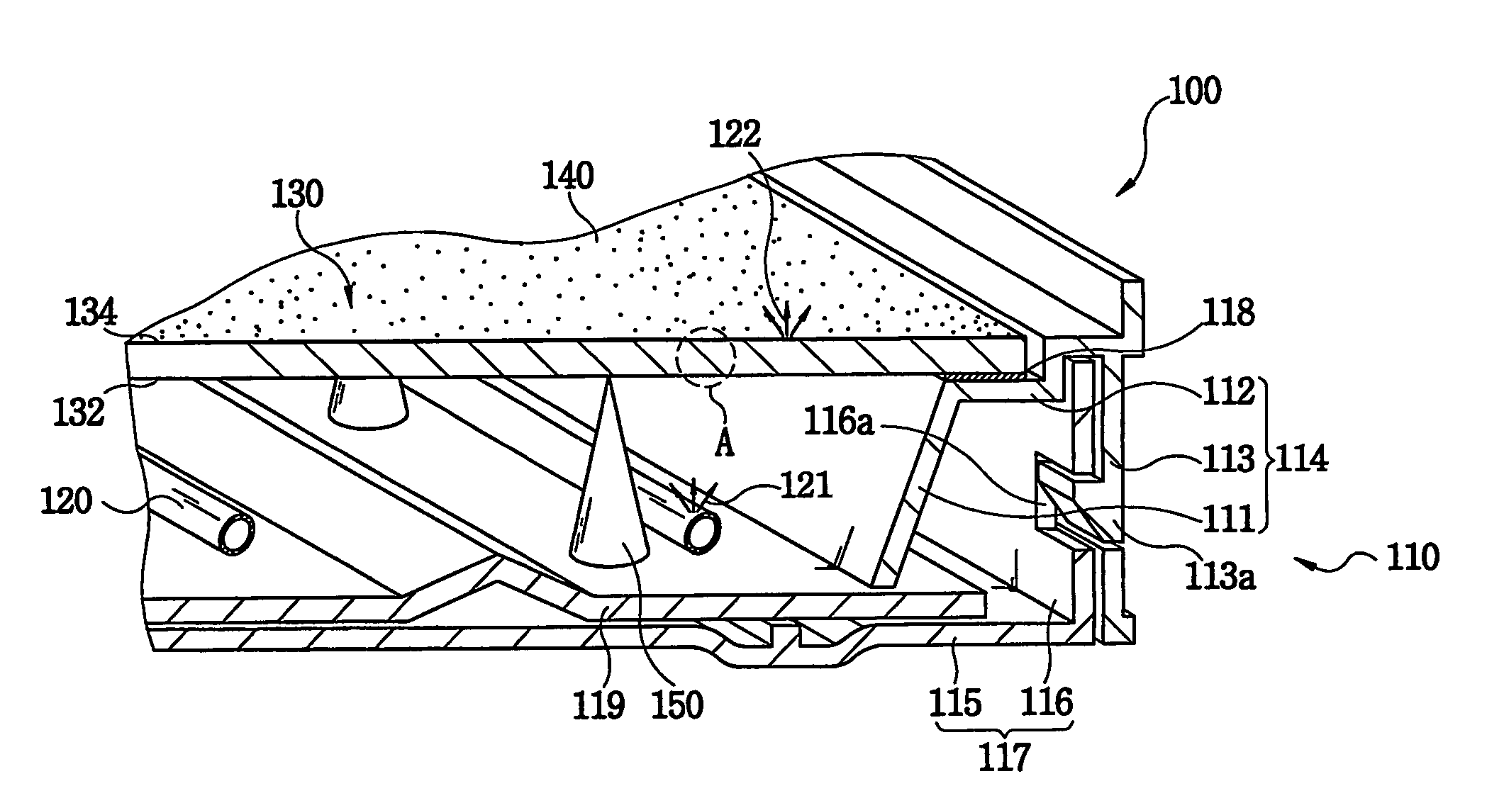
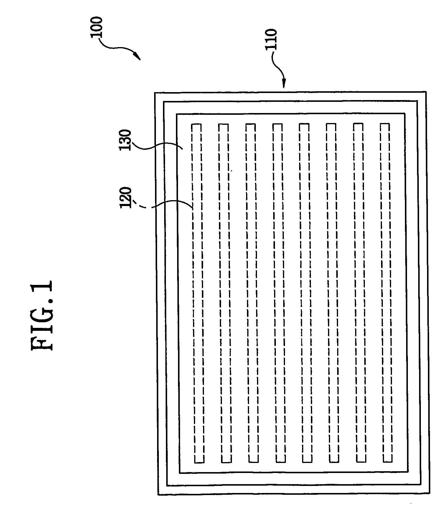
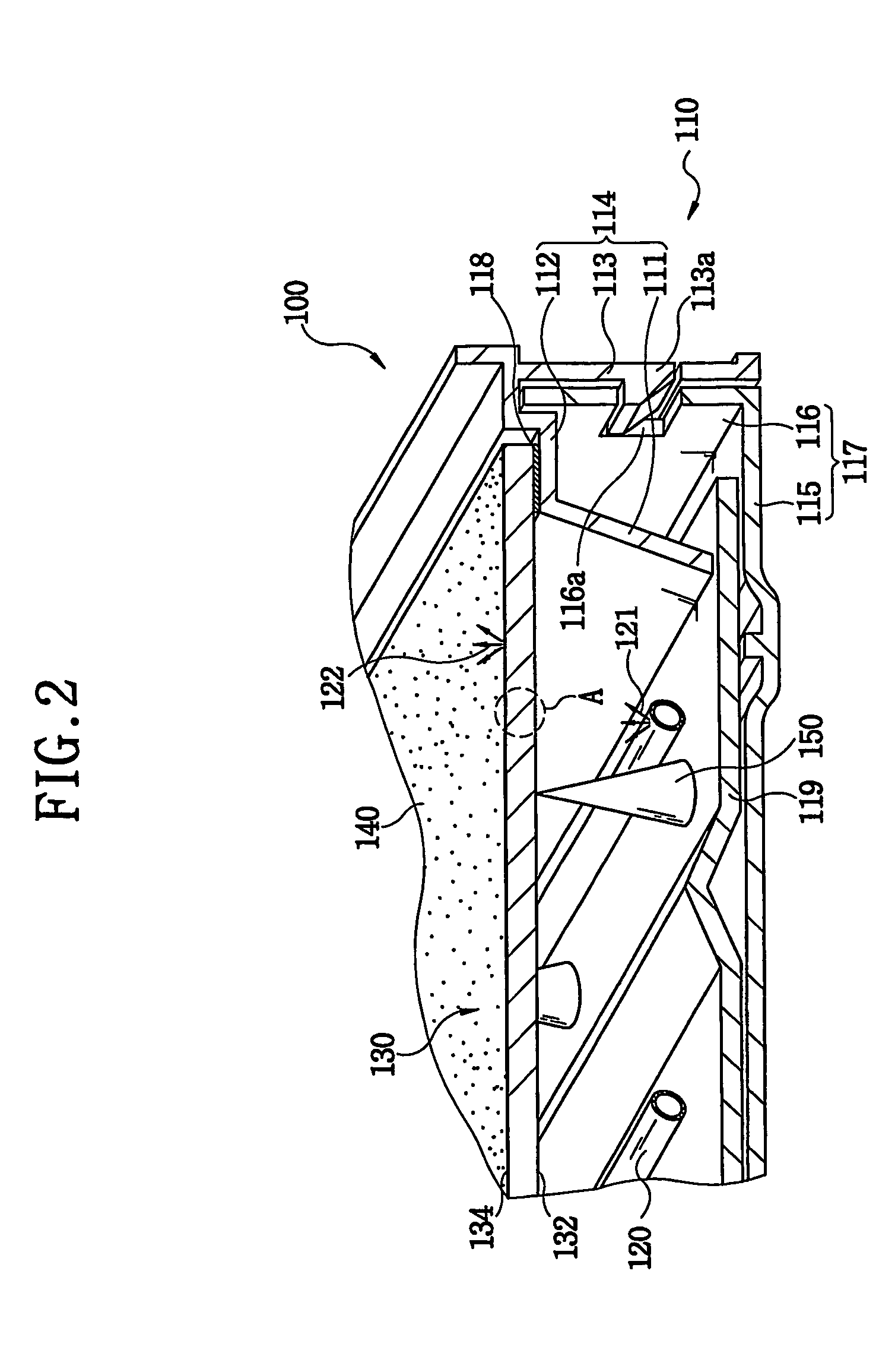
[0039]FIG. 1 is a top view showing a back light assembly according to an exemplary first embodiment of the present invention and FIG. 2 is a partially cut perspective view showing a back light assembly of FIG. 1.

[0040]Referring to FIGS. 1 and 2, a back light assembly 100 includes a receiving container 110, a lamp 120, a glass substrate 130 and a diffusion sheet 140.

[0041]The receiving container 110 has a receiving space for receiving the lamp 120, the glass substrate 130 and the diffusion sheet 140.

[0042]Referring to FIG. 2, the receiving container 110 includes a first receiving frame 114 and a bottom chassis 117. The first receiving frame 114 and the bottom chassis 117 form the receiving space.

[0043]The first receiving frame 114 includes a first plate 111, a second plate 112 and a third receiving plate 113.

[0044]The second plate 112 has a rectangular frame shape having an opening inside the rectangular frame. The glass substrate 130 and the diffusion sheet 140 are disposed on the s...

embodiment 2

[0072]FIG. 4 is a cross-sectional view showing a portion of a glass substrate according to an exemplary second embodiment of the present invention, and FIG. 5 is a cross-sectional view showing a portion of a glass substrate according to a modified second embodiment of the present invention.

[0073]Referring to FIGS. 2, 4 and 5, the glass substrate 130 is disposed on the second plate 112 of the first receiving frame 114. The diffusion sheet 146 is disposed on the glass substrate 130. The glass substrate 130 includes a first face 132 and a second face 134. Light generated by the lamp 120 is incident onto a first face 132 of the glass substrate 130. The first face 132 faces a second face 134 of the glass substrate 130.

[0074]Referring to FIG. 4, a light diffusion layer 146 is formed on the first face 132 of the glass substrate 130.

[0075]The light diffusion layer 146 includes a binder 146a and a light diffusion bead 146b. The binder 146a is transparent and adhesive. The light diffusion bea...

embodiment 3

[0083]FIG. 6 is a cross-sectional view showing a portion of a glass substrate according to an exemplary third embodiment of the present invention, and FIG. 7 is a cross-sectional view showing a portion of a glass substrate according to a modified third embodiment of the present invention.

[0084]A light diffusion portion 135 is formed on a glass substrate 130. For example, an impact-proof glass or a tempered glass may be used as the glass substrate 130. The tempered glass has a low thermal expansion coefficient. The tempered glass is impervious to external impact.

[0085]A first light 121 generated by the lamp 120 is incident onto a first face 132 of the glass substrate 130. The first face 132 faces a second face 134.

[0086]Referring to FIGS. 6 and 7, the light diffusion portion 135 is formed on the first face 132 or on the second face 134.

[0087]The light diffusion portion 135 may be formed via various manufacturing methods. For example, the light diffusion portion 135 may be formed via ...


PUM

PropertyMeasurementUnit
Hazeaaaaaaaaaa
thicknessaaaaaaaaaa
luminance distributionaaaaaaaaaa

Abstract

Disclosed are a back light assembly for preventing discoloration and deformation caused by heat generated from a lamp, and a liquid crystal display device for displaying an enhanced image. The back light assembly includes a receiving container, a lamp, a glass substrate and a diffuser. The receiving container has a receiving space. The lamp for generating the light is disposed in the receiving space. The glass substrate is interposed between the liquid crystal display panel and the lamp. The diffuser diffuses the light generated by the lamp so as to unify a luminance distribution of the liquid crystal display panel. The liquid crystal display device includes the back light assembly.

Description

TECHNICAL FIELD[0001]The present invention relates to a back light assembly, and a liquid crystal display device having the back light assembly, and more particularly to a back light assembly for preventing discoloration and deformation caused by heat generated from a lamp, and a liquid crystal display device displaying an enhanced image.BACKGROUND ART[0002]A liquid crystal display device displays an image processed by the information-processing device, so that a user can perceive the image.[0003]The liquid crystal display device, one of display devices, uses a liquid crystal, of which transmissivity is modulated according to electric fields so as to display an image.[0004]The liquid crystal modulates the light transmissivity only. Therefore, the liquid crystal display device needs light passing through the liquid crystal so as to display an image.[0005]A lamp generates the light. A Cold Cathode Fluorescent Lamp (CCFL) may be used as the lamp of the liquid crystal display device.[00...

Claims


Application Information

Patent Timeline
Patent Type & Authority Patents(United States)
IPC IPC(8): G02F1/1335G02F1/1333F21V8/00G02F1/13357
CPCG02F1/133604G02F1/133606G02F1/1335
Inventor LEE, JEONG-HWANLEE, KEUN-WOOPARK, JONG-DAEJUNG, JAE-HOLEE, TAE-JINBANG, CHANG-YOUNG
Owner SAMSUNG DISPLAY CO LTD
Learn More