
Method of detecting clipped image pixels

a technology of image pixels and detection methods, applied in the field of image processing, can solve the problems of not explaining the detection method, easy to produce visually objectionable artifacts corresponding to clipped pixels, and detract from the image quality

Active Publication Date: 2008-02-05
MONUMENT PEAK VENTURES LLC
View PDF33 Cites 53 Cited by
  • Summary
  • Abstract
  • Description
  • Claims
  • Application Information

AI Technical Summary

Benefits of technology

[0010]Since it is useful to know if a digital image has clipped pixel values, and where those pixels are located, the advantage of the invention is that, when manipulating an image, having knowledge of the location of all, or most, clipped pixels makes it more feasible to avoid producing visually objectionable artifacts corresponding to such clipped pixels of the digital image.

Problems solved by technology

Clipping usually detracts from the quality of the image.
When manipulating an image, it is especially easy to produce visually objectionable artifacts corresponding to clipped pixels of the digital image.
This method does not explain how to detect whether the image contains a clipped pixel component.
However, it is incorrect to assume that the detection of clipped pixels is a simple problem that can be solved with only a thresholding operation.
Thus, none of the prior art methods of detecting clipped pixels are adequate, because either some clipped pixels would be misclassified as non-clipped, or some non-clipped pixels would be misclassified as clipped.
Thus, clipping can occur at many different points, and a simple threshold is inadequate to detect clipped pixels.

Method used


Image

  • Method of detecting clipped image pixels
  • Method of detecting clipped image pixels
  • Method of detecting clipped image pixels

Examples


Embodiment Construction

[0016]In the following description, a preferred embodiment of the present invention will be described as a software program. Those skilled in the art will readily recognize that the equivalent of such software may also be constructed in hardware. Because image manipulation algorithms and systems are well known, the present description will be directed in particular to algorithms and systems forming part of, or cooperating more directly with, the method in accordance with the present invention. Other aspects of such algorithms and systems, and hardware and / or software for producing and otherwise processing the image signals involved therewith, not specifically shown or described herein may be selected from such systems, algorithms, components, and elements known in the art. Given the description as set forth in the following specification, all software implementation thereof is conventional and within the ordinary skill in such arts.

[0017]The present invention may be implemented in c...


PUM


Abstract

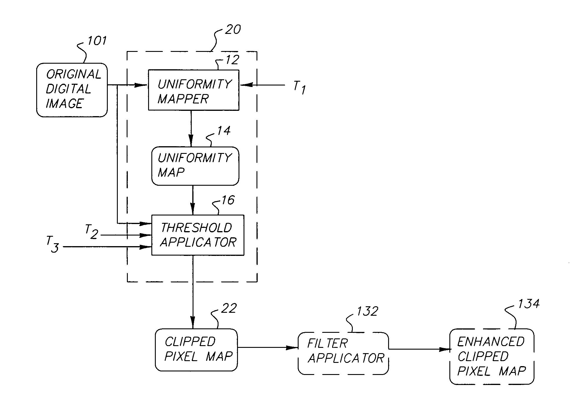
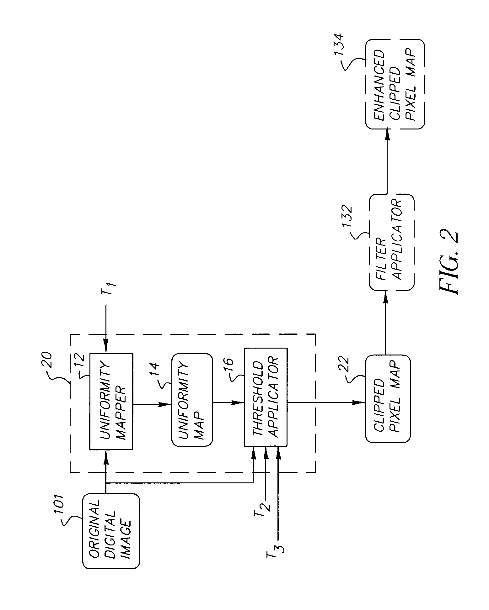
A method is described for detecting the clipped pixels of a digital color image. The method includes the steps of: (a) producing a uniformity map from the digital color image, where the uniformity map indicates locations within the digital color image that are substantially uniform; (b) providing a threshold value; and (c) using the uniformity map, the threshold value, and the digital color image to produce a map indicating the location of clipped pixels within the digital color image.

Description

FIELD OF THE INVENTION[0001]The present invention relates to the field of image processing, and in particular to the improvement of images that are subject to clipping.BACKGROUND OF THE INVENTION[0002]In a digital image, clipping appears as a uniform area. Clipping usually detracts from the quality of the image. A pixel can be clipped in only one color channel, or simultaneously in multiple or all color channels.[0003]Clipping can result from a number of causes. Numerical clipping occurs when the value of the pixel reaches a limit of an allowable range. In an 8-bit per pixel per color channel system, numerically clipped regions appear as pixels having a value of 0 or 255. Clipping can occur from saturation, meaning that at some point in the image processing path, the pixel value (in either analog or digital form) reaches a limiting value. For example, if photosites of an imaging sensor are saturated, then the digital value from the A / D converter will be some maximum value.[0004]It i...

Claims


Application Information

Patent Timeline
IPC IPC(8): G06F15/00G03F3/08H04N9/64
CPCH04N9/646
Inventor GALLAGHER, ANDREW C.
Owner MONUMENT PEAK VENTURES LLC
Learn More