
Audio decoding method and apparatus which recover high frequency component with small computation

a high frequency component and audio decoding technology, applied in the field of audio decoding methods and auxiliary equipment which recover high frequency components with small computation, can solve the problems of depressed or dull sounds, loss of high frequency components, and deformation of sound clarity, so as to reduce the amount of computation

Inactive Publication Date: 2008-02-05
SAMSUNG ELECTRONICS CO LTD
View PDF9 Cites 28 Cited by
  • Summary
  • Abstract
  • Description
  • Claims
  • Application Information

AI Technical Summary

Benefits of technology

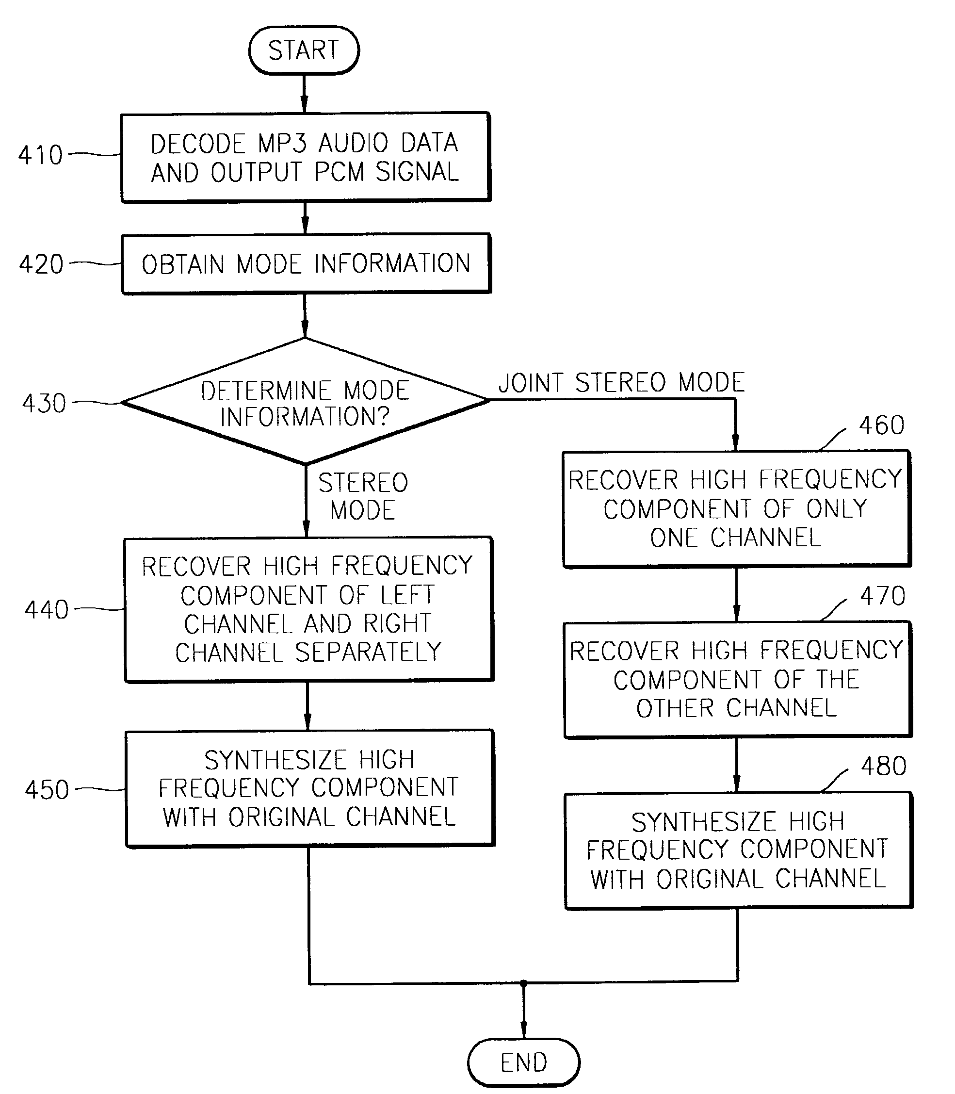
The present invention provides a new audio decoding method and apparatus that reduces the excessive computation needed in prior art post processing methods. The method uses mode information to recover high frequency components of a signal in a left channel and a signal in a right channel in MPEG-1 layer 3 audio data. The high frequency component can be recovered by selecting a mode based on the difference between the two channel signals. The recovered high frequency component can be used to recover the high frequency component of the other channel when the difference between the two channel signals is small. Alternatively, the high frequency component in only one of every two frames can be recovered alternately in the left channel and the right channel, and the high frequency component of each skipped frame can be interpolated based on the high frequency components of the previous frame and the next frame when the difference between the two channel signals is big. This results in a more efficient and accurate audio decoding process.

Problems solved by technology

In this case, although the compression ratio improves, high frequency components are lost.
Because of the loss of the high frequency components the tone changes and the clarity of sound degrades such that depressed or dull sounds are output.
However, despite their high sound quality conventional post processing sound quality improving methods need an excessive amount of computation to perform the post processing methods.
In addition, the effect of reducing the amount of computation in performing the post processing method cannot be achieved in the prior art method.

Method used


Image

  • Audio decoding method and apparatus which recover high frequency component with small computation
  • Audio decoding method and apparatus which recover high frequency component with small computation
  • Audio decoding method and apparatus which recover high frequency component with small computation

Examples


Embodiment Construction

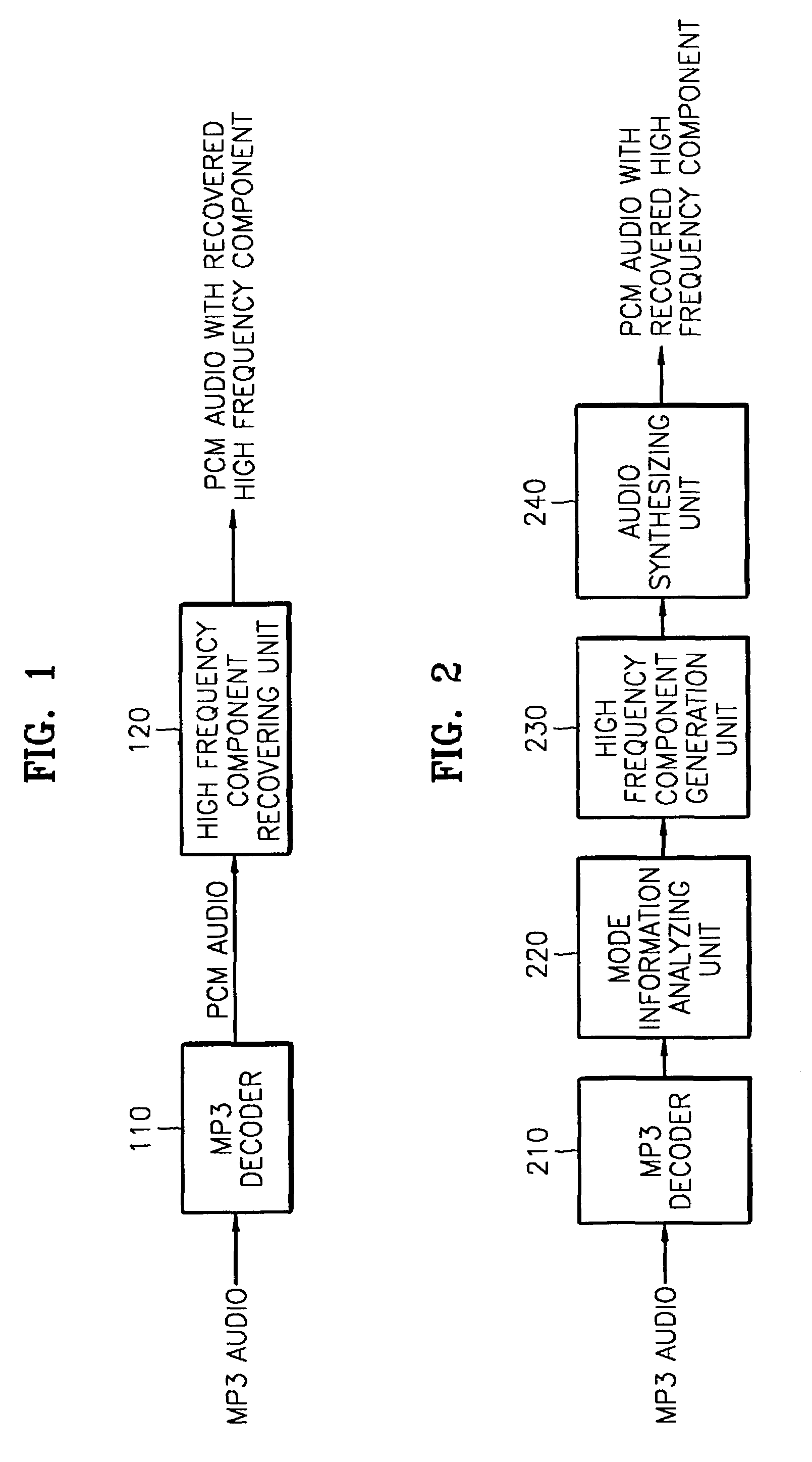
[0021]Referring to FIG. 1, an audio data that is encoded complying with the MPEG-1 layer 3 (MP3) format is input to an MPEG-1 layer 3 decoder 110 which divides the data into a left channel component and a right channel component and generates respective pulse code modulation (PCM) data. The PCM data is input to a high frequency component recovering unit 120 which recovers the high frequency component of each of the left channel and right channel, and outputs recovered PCM audio data.

[0022]Thus, in the prior art post processing method, a high frequency domain is recovered by post processing the left channel signal and the right channel signal, respectively, which are output through the MPEG-1 layer 3 decoder 110.

[0023]However, in most audio signals, there is a high degree of redundancy between a left channel signal and a right channel signal. Accordingly, even in the MPEG-1 layer 3 encoding algorithm, a left channel signal and a right channel signal are not encoded independently in j...


PUM

PropertyMeasurementUnit
frequencyaaaaaaaaaa
compression ratioaaaaaaaaaa
frequency resolutionaaaaaaaaaa

Abstract

A method and apparatus for performing audio post processing using mode information that indicates the degree of similarity between a right channel signal and a left channel signal in MPEG-1 layer 3 audio data, are provided. If the difference between the two channel signals is small, a first mode is used in which the high frequency component of only one channel is recovered and the recovered high frequency component is used to recover the high frequency component of the other channel. If the difference between the two channel signals is large, a second mode is selected in which the high frequency component in only one of every two frames is recovered alternately in the left channel and the right channel and the high frequency component of each of the skipped frames is interpolated based on the high frequency components of the previous frame and the next frame.

Description

CROSS-REFERENCE TO RELATED APPLICATIONS[0001]This application is based upon and claims priority from Korean Patent Application No. 2002-40402 filed Jul. 11, 2002, the contents of which are incorporated herein by reference.BACKGROUND OF THE INVENTION[0002]1. Field of the Invention[0003]The present invention relates to a method and apparatus which reduce the amount of computation in audio post-processing, and more particularly, to a method and apparatus which recover a high frequency component in MPEG-1 layer 3 audio using stereo mode information detected in a decoder, by selecting a mode depending on a circumstance after dividing stereo modes into two modes. In a first mode, the high frequency component of only one channel is recovered and the recovered high frequency component is used to recover the high frequency component of the other channel when the difference between the two channel signals is small. In a second mode, the high frequency component in only one of every two frames...

Claims


Application Information

Patent Timeline
Patent Type & Authority Patents(United States)
IPC IPC(8): G10L19/00G06F17/00G10L21/00H04B1/00H04R5/00G10H1/00G10H1/12G10L19/02G11B20/00H04S1/00
CPCH04S1/007G10H1/0091G10H1/125G11B20/00007G11B20/00992G11B20/00086G10L19/008G10L19/02
Inventor OH, YOON-HAK
Owner SAMSUNG ELECTRONICS CO LTD
Learn More